–
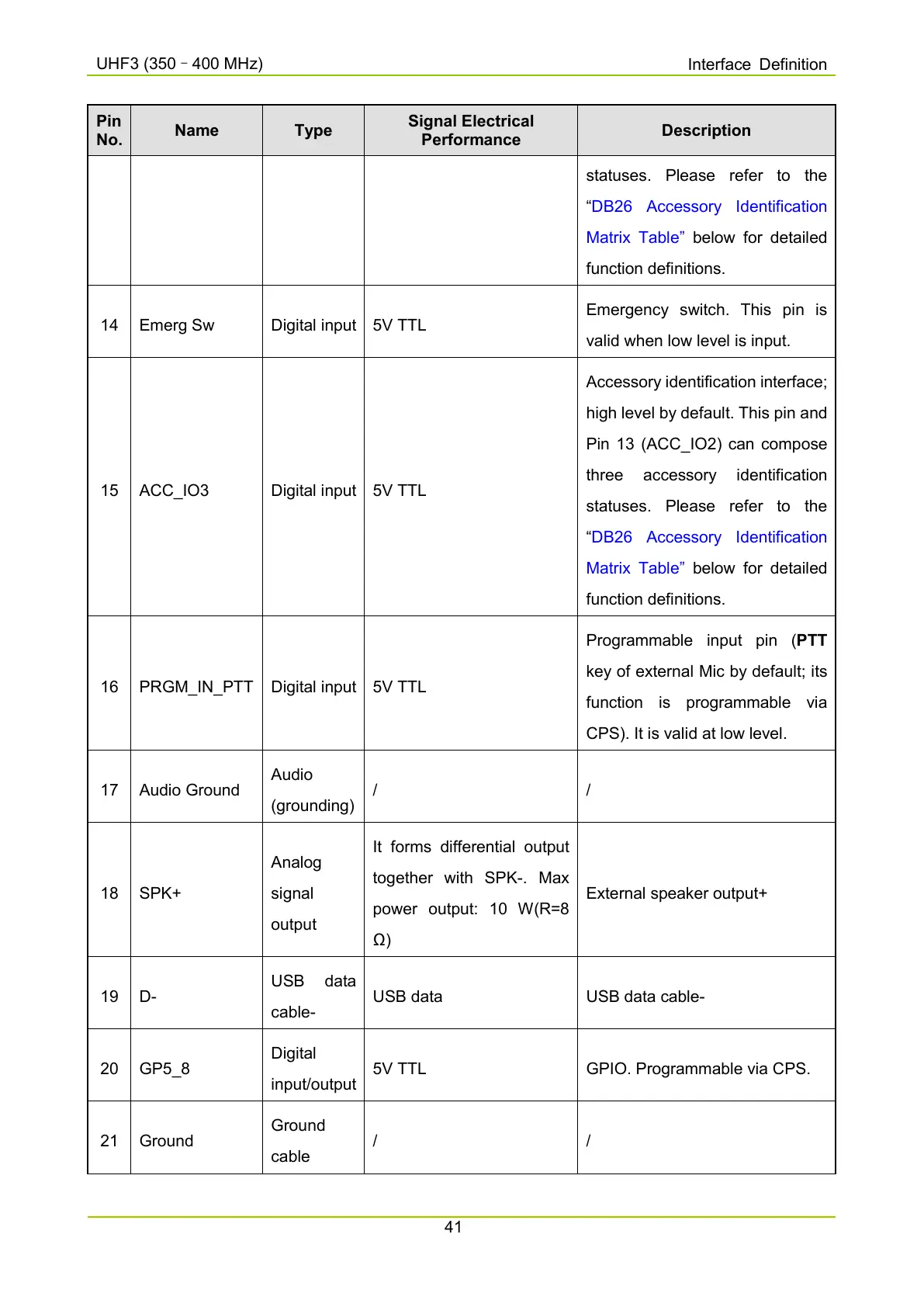
Pin
No.
Name Type
Signal Electrical
Performance
Description
statuses.
“
DB26 Accessory Identification
Matrix Table”
function definitions.
14 Emerg Sw Digital input
5V TTL
Emergency switch. This pin is
valid when low level is input.
15 ACC_IO3 Digital input 5V TTL
Accessory identification interface;
high level by default. This pin and
Pin 13 (ACC_IO2) can compose
three a
ccessory identification
statuses. Please refer to the
“
DB26 Accessory Identification
Matrix Table”
function definitions.
16 PRGM_IN_PTT Digital input
5V TTL
Programmable input pin (PTT
key of external Mic by default; its
function is programmable via
CPS). It is valid at low level.
17 Audio Ground
Audio
(grounding)
/ /
18 SPK+
Analog
signal
output
It forms differential output
together with SPK-
. Max
power output: 10 W(R=8
Ω)
External speaker output+
19 D-
cable-
USB data USB data cable-
20 GP5_8
Digital
input/output
5V TTL GPIO. Programmable via CPS.
21 Ground
Ground
cable
/ /

 Loading...


