–
5.2 Baseband
5.2.1
Power Supply Module
ON\OFF KEY PWB
IGN_SENCE
EMERGENCY
Q801Q810
Q6102
Q6103
Q902
Q804\Q805
Q802\Q803\U201\Q909
U703 U701
U702 U701
U915 Q104 Q100\Q103\Q106\Q110
U918
U100
X100
U905
U500
U909
U231
X302
U302
U401 USB
Control Head
Accessory Level
Translator
Option board
U919
U902
U900
U903
U901
U302
U233
U910
U500
U231
U327
U231
U232
U302
U326
Q920\Q921\U914
Auto baterry
Voltage
13.6±15%
9V3A
9V1A
9V1A
5VA
4V3A
3V3A
5VA
3V3A
1V6D
5VD
3V3D
1V8D
3V3DP
3V3A
5VA
5VA
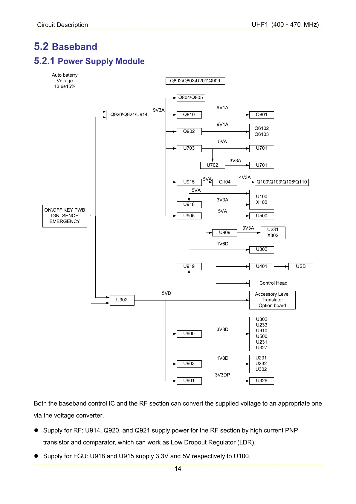
Both the baseband control IC and the RF section can convert the supplied voltage to an appropriate one
via the voltage converter.
Supply for RF: U914, Q920, and Q921 supply power for the RF section by high current PNP
transistor and comparator, which can work as Low Dropout Regulator (LDR).
Supply for FGU: U918 and U915 supply 3.3V and 5V respectively to U100.

 Loading...


