–
Pin No. Signal Function
I/O of the
Radio
Voltage
(Option Board
VDD=3.3 V)
Remark
board)
19 DGND DGND / / /
20 3V6 or 5V Power O Voltage: 5.0 V /
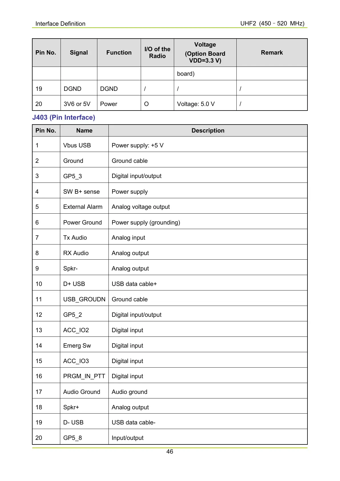
J403 (Pin Interface)
Pin No. Name Description
1 Vbus USB Power supply: +5 V
2 Ground Ground cable
3
GP5_3
Digital input/output
4 SW B+ sense Power supply
5 External Alarm Analog voltage output
6 Power Ground Power supply (grounding)
7 Tx Audio Analog input
8 RX Audio Analog output
9 Spkr- Analog output
10 D+ USB USB data cable+
11 USB_GROUDN Ground cable
12
GP5_2
Digital input/output
13 ACC_IO2 Digital input
14 Emerg Sw Digital input
15 ACC_IO3 Digital input
16 PRGM_IN_PTT Digital input
17 Audio Ground Audio ground
18 Spkr+ Analog output
19 D- USB USB data cable-
20
GP5_8
Input/output

 Loading...