–
Step 2 U917 generates reset signal and remains low level for 1.25 seconds, allowing the processor
(U302) to get started.
Step 3 Power-on signal is sent to the processor (U302).
Step 4 After receiving the signal, the processor (U302) generates the level of PWR_CTRL. Then the
power-up procedures are completed.
Clock
Option Board
U231
U302
32.768KHz
32K
32K_IN
VSS
CLK32K_IN
APLL
19.2MHz 9.6MHz
DAC
U100
19.2MHz
U701
19.2MHz
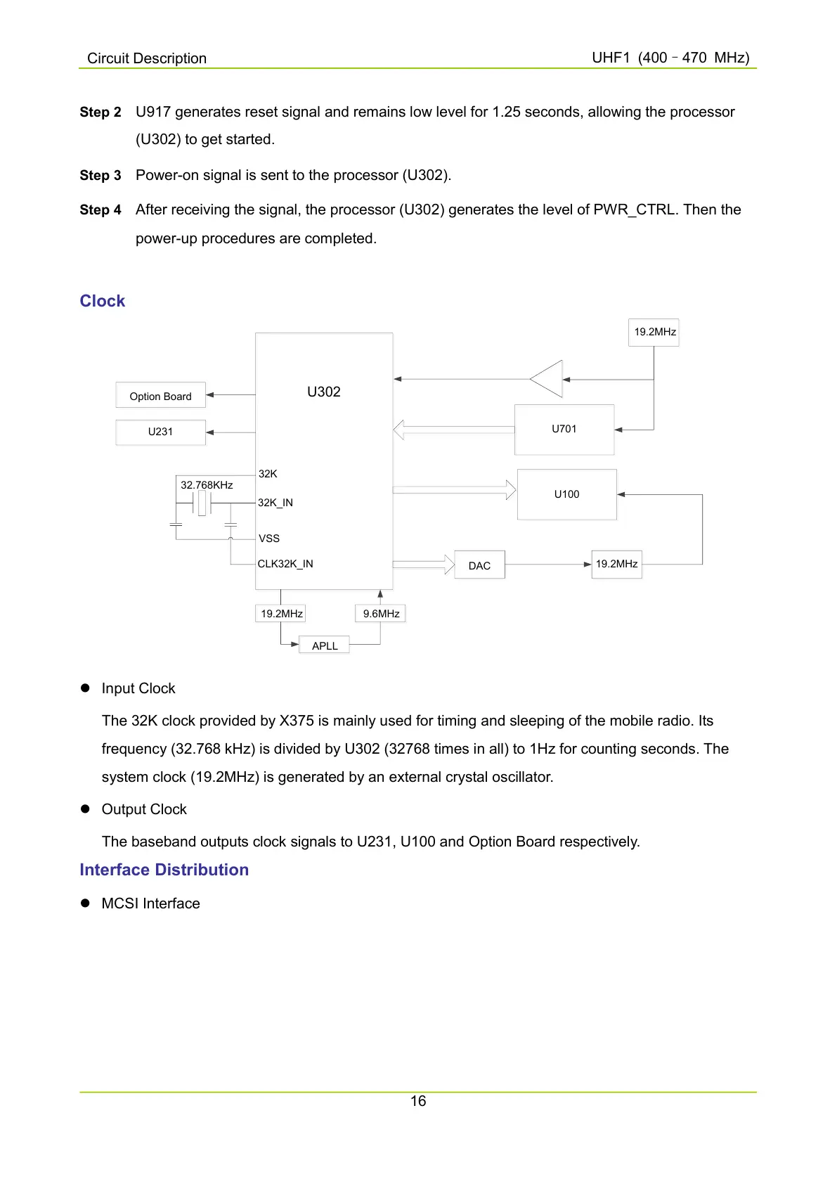
Input Clock
The 32K clock provided by X375 is mainly used for timing and sleeping of the mobile radio. Its
frequency (32.768 kHz) is divided by U302 (32768 times in all) to 1Hz for counting seconds. The
system clock (19.2MHz) is generated by an external crystal oscillator.
Output Clock
The baseband outputs clock signals to U231, U100 and Option Board respectively.
Interface Distribution
MCSI Interface

 Loading...


