–
Registers
MSB/LSB
Dividend
Divider
PD/Charge Pump
& Pwr-Dn/Mux Out
Control
Reference
Frequency Dividers
Serial
Interface
Modulation
Unit
Fractional
Unit
ΔΣ
18-Bit
Main
Divider
Main
Divider
Main Phase/
Freq.Detector
and
Charge Pump
Reference
Frequency
Oscillator
Reference
Frequency
Oscillator
M
u
x
Mux_out
Ref
Data
Clock
CS
Mod_in
Fvco_main
Fvco_main
CPout_main
LD/PS_main
Lock Detection or
Power Steering
Fref_main
Fref_main
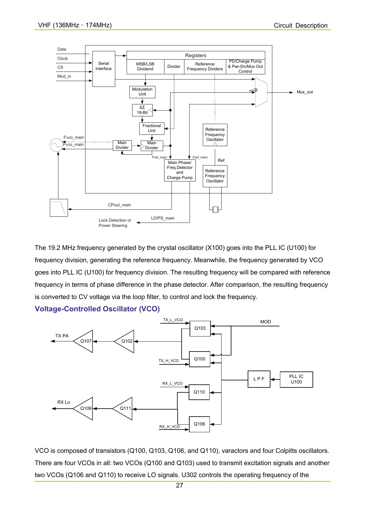
The 19.2 MHz frequency generated by the crystal oscillator (X100) goes into the PLL IC (U100) for
frequency division, generating the reference frequency. Meanwhile, the frequency generated by VCO
goes into PLL IC (U100) for frequency division. The resulting frequency will be compared with reference
frequency in terms of phase difference in the phase detector. After comparison, the resulting frequency
is converted to CV voltage via the loop filter, to control and lock the frequency.
Voltage-Controlled Oscillator (VCO)
PLL IC
U100
Q103
L P F
Q110
Q100
Q106
Q102
Q107
MOD
Q111Q109
TX_L_VCO
RX_L_VCO
TX_H_VCO
RX_H_VCO
TX PA
RX Lo
VCO is composed of transistors (Q100, Q103, Q106, and Q110), varactors and four Colpitts oscillators.
There are four VCOs in all: two VCOs (Q100 and Q103) used to transmit excitation signals and another
two VCOs (Q106 and Q110) to receive LO signals. U302 controls the operating frequency of the

 Loading...


