–
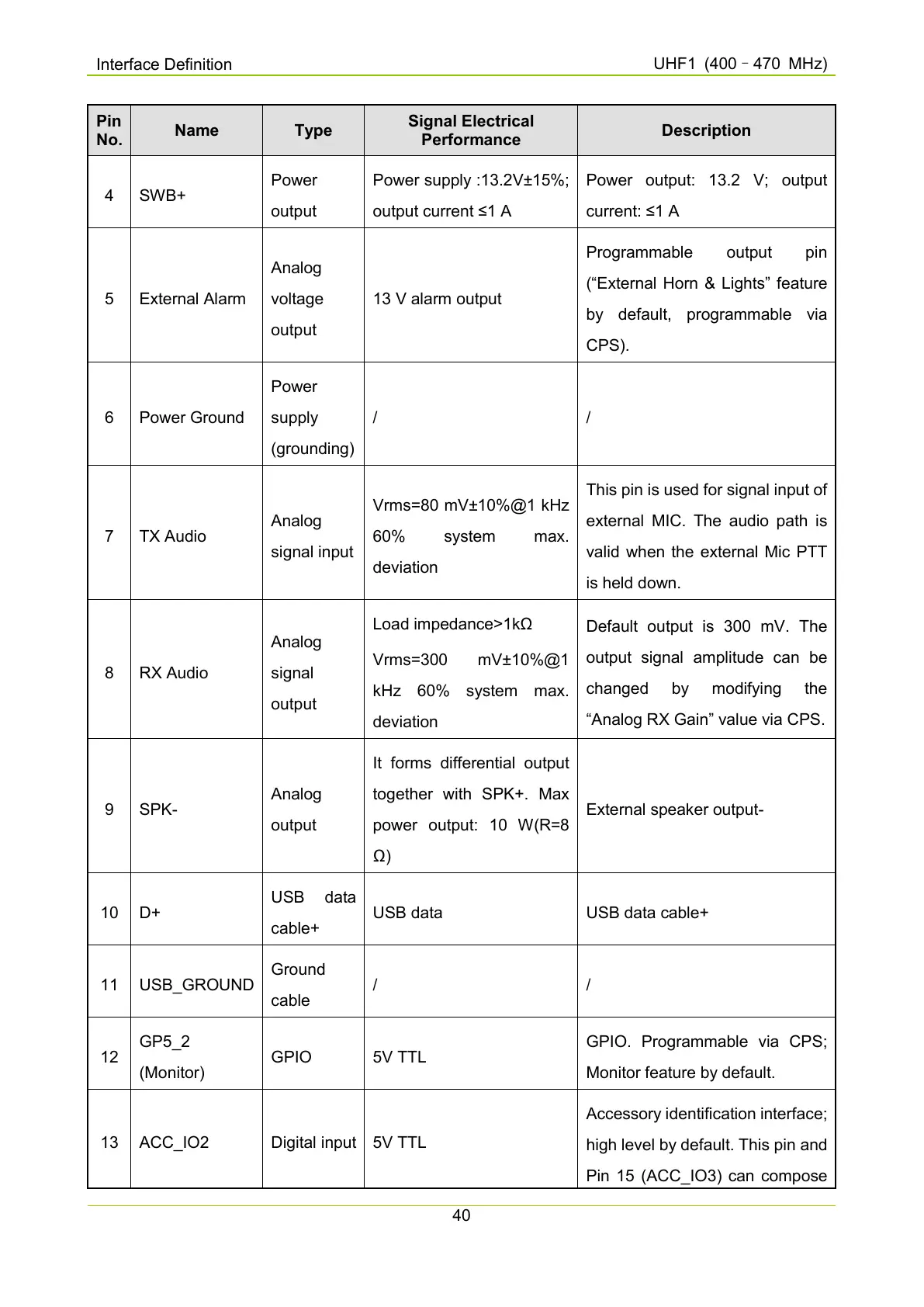
Pin
No.
Name Type
Signal Electrical
Performance
Description
4 SWB+
Power
output
Power supply :13.2V±15%;
output current ≤1 A
Power output: 13.2 V; output
current: ≤1 A
5 External Alarm
Analog
voltage
output
13 V alarm output
Programmable output pin
(“External Horn & Lights” feature
by default, programmable via
CPS).
6 Power Ground
Power
supply
(grounding)
/ /
7 TX Audio
Analog
signal input
Vrms=80 mV±10%@1 kHz
deviation
This pin is used for signal input of
external MIC. The audio path is
valid when the external Mic PTT
is held down.
8 RX Audio
Analog
signal
output
Load impedance>1kΩ
Vrms=300 mV±10%@1
kHz
deviation
Default
output is 300 mV. The
output signal amplitude can be
changed by modifying the
“Analog RX Gain” value via CPS.
9 SPK-
Analog
output
It forms differential output
together with SPK+. Max
power output: 10 W(R=8
Ω)
External speaker output-
10 D+
cable+
USB data USB data cable+
11 USB_GROUND
Ground
cable
/ /
12
GP5_2
(Monitor)
GPIO 5V TTL
GPIO. Programmable via CPS;
Monitor feature by default.
13 ACC_IO2 Digital input
5V TTL
Accessory identification interface;
high level by default. This pin and
Pin 15 (ACC_IO3) can compose

 Loading...


