Service Manual Baseband Section
11
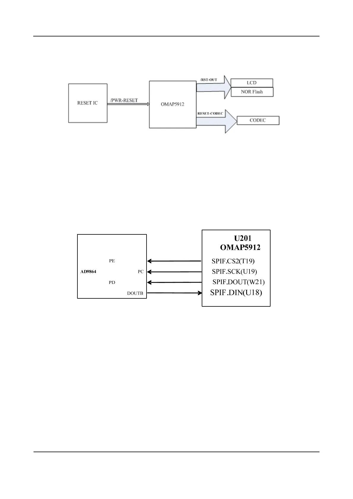
3.2.4 Reset signal
Figure 3-7 Diagram of Reset Signal
3.2.5 SPI
OMAP5912 has a SPI, which has four chip-selects for connecting four external SPI components. The
SPI signals available are SPI.DOUT, SPI.DIN, SPI.CLK and SPI.CS. The system uses SPIF.CS2 to
select the IF processor AD9864, to configure register of AD9864. The connection of SPI is shown
below.
Figure 3-8 Diagram of SPI Connection
3.2.6 MCBSP
OMAP5912 provides 3 MCBSP interfaces: MCBSP1, MCBSP2 and MCBSP3. MCBSP1 is connected
with the I2S interface of the audio codec, to realize two-way transmission of digital voice and data.
MCBSP2 uses independent clock and frame synchronization for transmission and reception. AD9864
SSI is connected to the RX end of OMAP5912 MCBSP2. AD9864 works in master mode, while DSP
works in slave mode. DAC is connected with the TX end of MCBSP2, and DSP works in master mode.
MCBSP3 is connected to the option board. The connection of MCBSP is shown below.
 Loading...