Service Manual Baseband Section
17
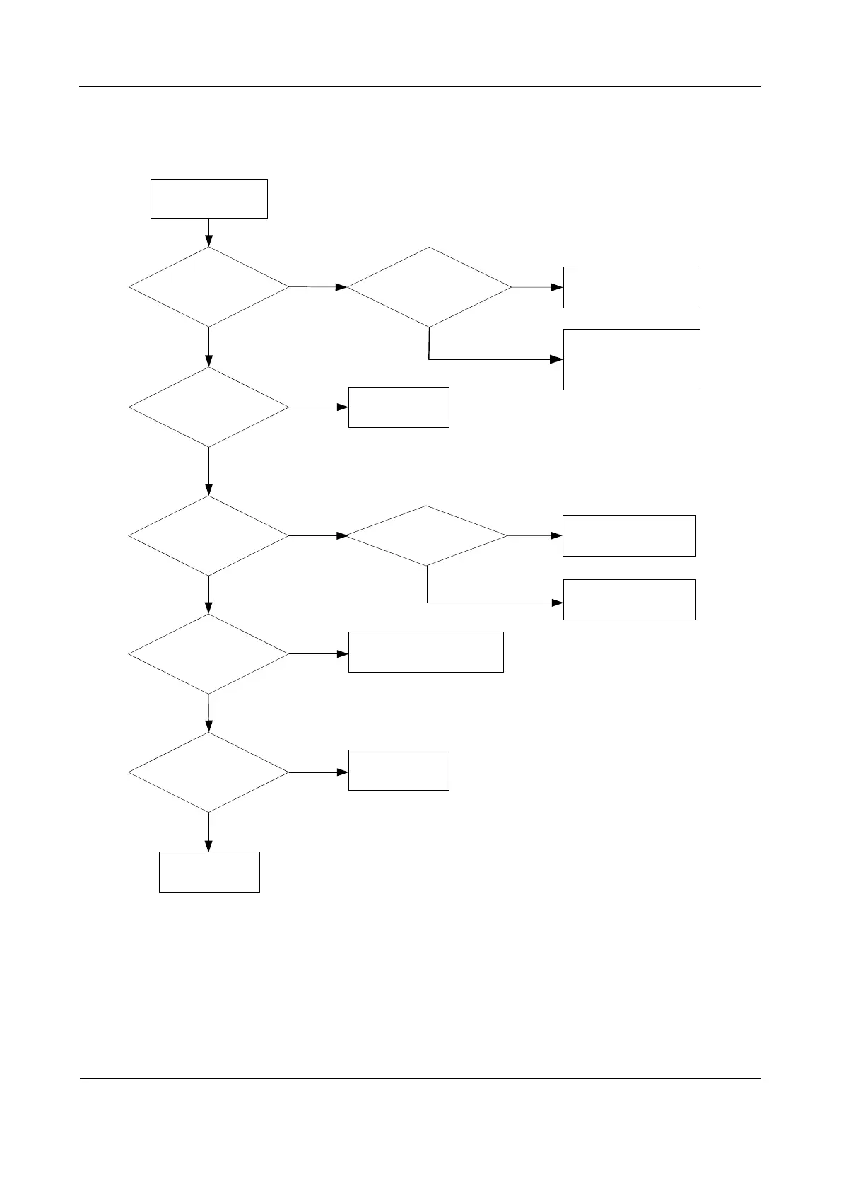
3.4 Troubleshooting Flow Chart
Control circuit
check
Normal
power-on display and
indication?[1]
Check the RF circuit
(U603, U604 and U605)
and control circuit.
LCD and LED work
normally?
3V3D voltage
is normal?
Replace LCD and
LED.
Check U601 and U609.
Reset
Check the power-on circuit
and U611.
Check U610
Yes
No
Yes
No
Yes
Yes
No
No
Yes
No
No
19.2MHz crystal works
normally?[3]
1V6D voltage is normal?
1V8D voltage is normal?
The control circuit works
normally.
The RF circuit is driven
normally?[2]
Yes
No
Yes
Completed
Description of Normal Situations:
[1] The radio shows normal power-on screen, and the backlight is normal.
[2] The RF power supply outputs normally, and the RX channel is on.
[3] Vpp: 700mV~800mV, F: 19.2MHz.
 Loading...