Service Manual GPS Circuit
19
4. GPS Circuit
4.1 Circuit Description
GPS
module
BPFHPF
LNA
OMAP
UART
TX/RX
LCD
Power
control
REB-1315LPx
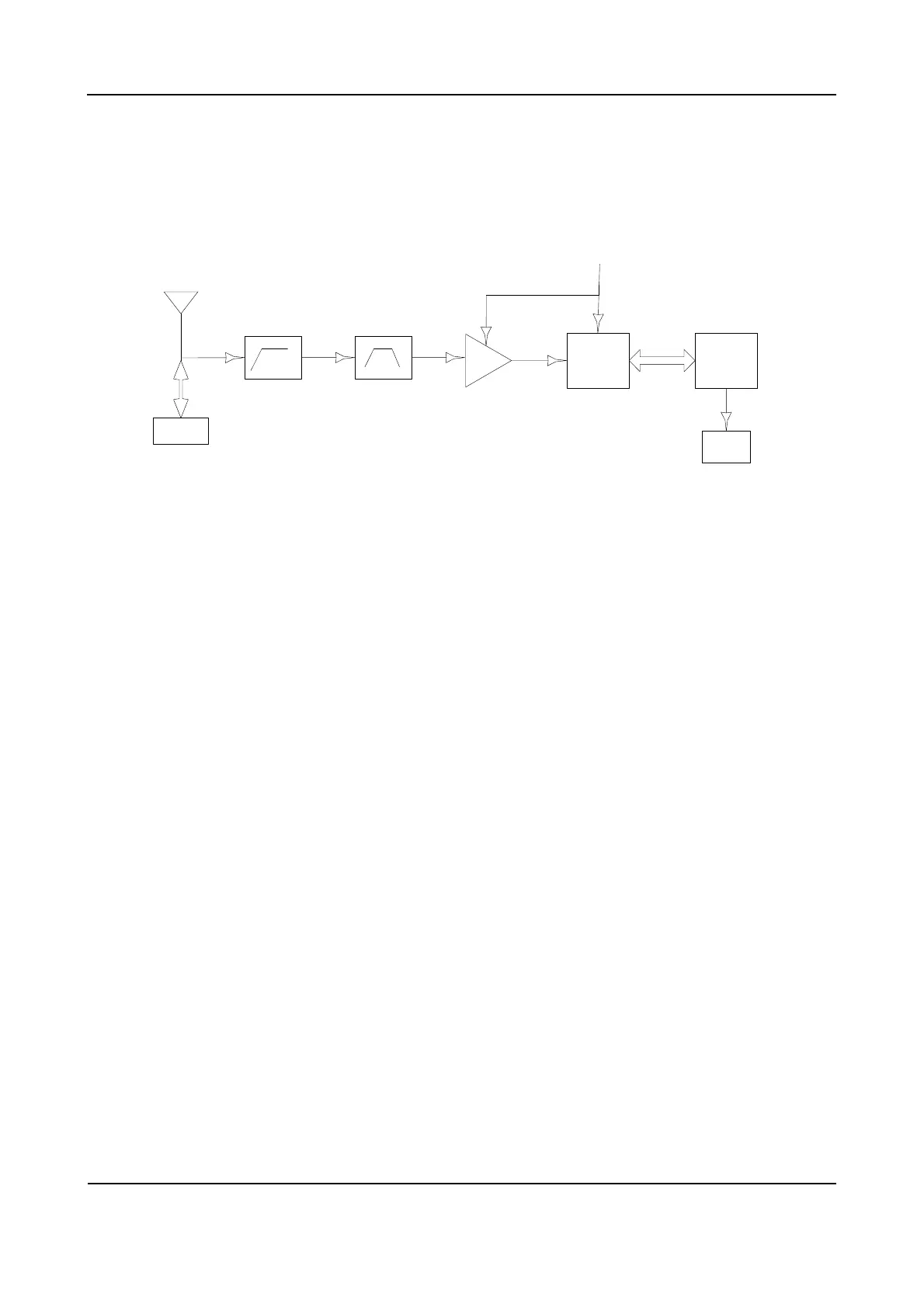
Figure 4-1 Diagram of GPS Circuit
The GPS function is realized via REB-1315LPx. The GPS circuit integrates a baseband processor, a
LNA and a SAW. The GPS function is realized via the following steps:
Step 1 The 1575.42MHz GPS signal is received by the antenna, and then goes to HPF to remove the
in-band signals used for transmission and reception.
Step 2 The signal goes to BPF to further remove in-band signals, as well as harmonic and spurious
signals.
Step 3 The weak GPS signal goes to a low-noise amplifier (LNA) for amplification.
Step 4 After amplified, the signal goes to the GPS module for further amplification and filtering, and is
then sent to the baseband section for calculation.
Step 5 The calculated GPS positioning information is sent to OMAP via the UART interface. Meanwhile,
OMPA can send appropriate command information to the GPS module via the UART interface.
Step 6 Finally, the OMAP sends the processed data information to the LCD.
 Loading...