Service Manual UHF5 (806-941MHz) Information
305
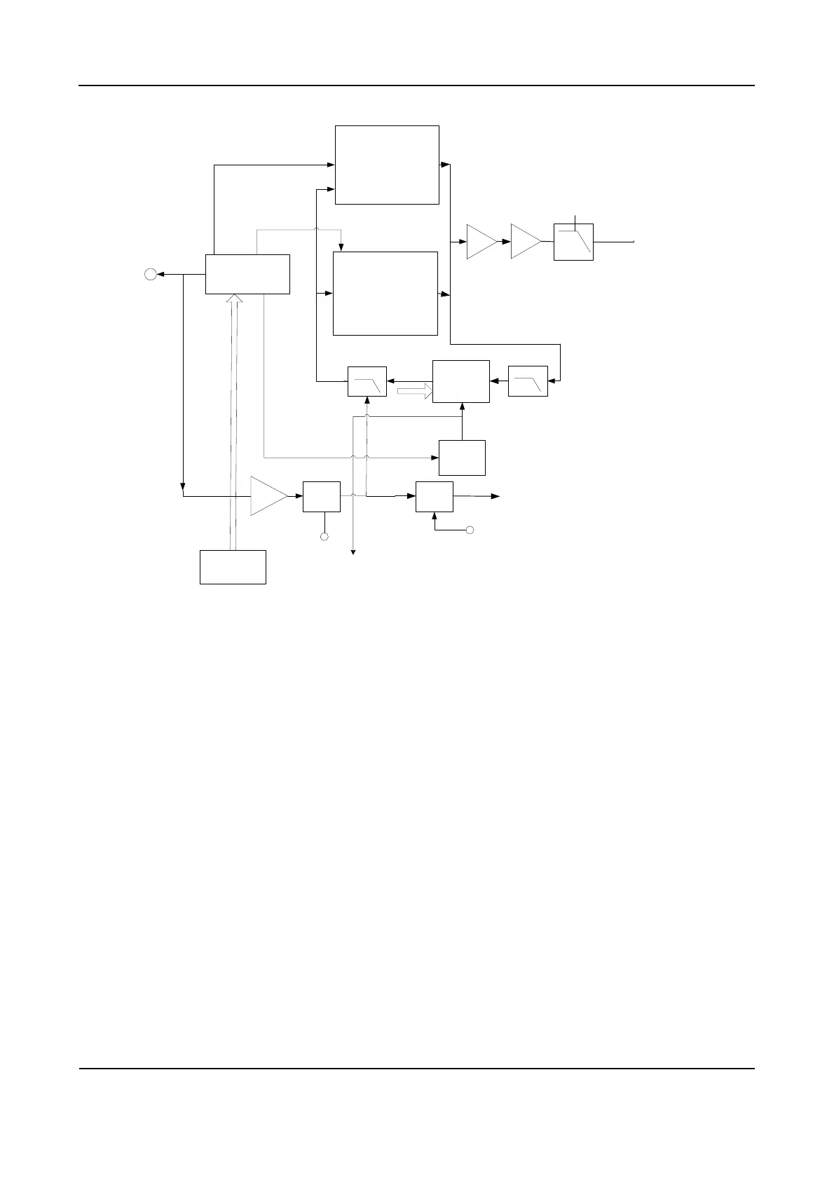
Low VCO
Frequency
Synthesizer
High VCO
Ref. Osc
19.2MHZ
.
MOD-VCO
MOD2+Freq error shift
4CH DAC
4pole RC filter
VCO
amplifier
From OMAP
Reference OSC signal
CV Buffer
Adapt
SW
Adapt
control
OP
VCO buffer
LPF
LPF
CV
SW
CV-read
control
CV out
VCO-OUT PUT
OMAP
MOD-VCO
Figure 10-4 Diagram of FGU
10.3.1 Working Principle of PLL
The 19.2MHz frequency generated by the reference crystal oscillator goes to PLL for division,
generating the reference frequency (i.e. step frequency f1). Meanwhile, the frequency generated by the
VCO generates another frequency (f2) through the frequency divider in PLL. Then frequencies f1 and f2
are compared in the phase detector (PD), to generate continuous pulse current. The current goes to the
loop filter for RC integration, and is then converted to CV voltage. Then the CV voltage is sent to the
varactor of VCO. It adjusts the output frequency of VCO directly until the CV voltage becomes constant.
Then the PLL is locked, and the stable frequency output by VCO goes to the TX-RX channel after
passing through the buffer amplifier.
10.3.2 Working Principle of VCO
VCO employs Colpitts oscillator circuit (the high oscillator circuit is composed of D102, D103, D106,
D107 and DR1; the low oscillator circuit is composed of D108, D109, D110, D101 and DR2). It obtains
different output frequencies by changing the varactor's control voltage (i.e. CV voltage).
There are two types of VCO: high VCO and low VCO. Both types control EMD22 to switch operating
 Loading...