Service Manual UHF5 (806-941MHz) Information
303
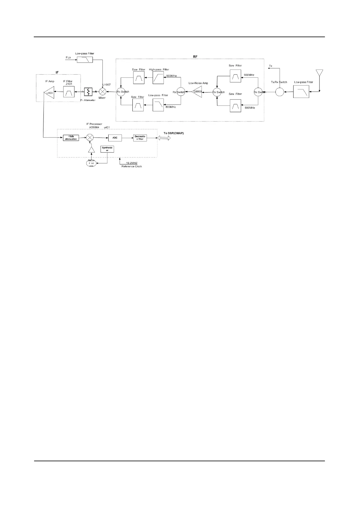
Figure 10-2 Diagram of Receiver Circuit
10.2.1 Receiver Front-end
The HF signal from the low-pass filter passes through the RX switch, which switches the signal to the
800MHz or 900MHz channel. Then the signal goes to the first SAW filter, to remove out-of-band
interference signal and to send wanted band-pass signal to the low-noise amplifier (Q9009). The
amplified signal goes to the second SAW filter, to remove out-of-band interference signal generated
during amplification, and to send wanted HF signal to the mixer.
The wanted signal passes through the RF band-pass filter and low-noise amplifier and goes to the mixer
(U1007). Meanwhile, the first local oscillator (LO) signal generated by VCO passes through the low-pass
filter and also goes to the mixer (U1007). In the mixer, the wanted signal and the first LO signal are
mixed to generate the first IF signal (73.35 MHz). Then the signal passes through a π-type attenuator
(2dB) and the LC, to suppress carrier other than the first IF signal, and to increase the isolation between
the mixer and the IF filter. After that, the first IF signal is processed by the crystal filter (Z9001), and is
sent to the two-stage IF amplifier circuit (composed of PBR941) for amplification. Then the amplified
signal goes to the IF processor AD9864(U401) for processing.
 Loading...