Service Manual UHF3 (350-400MHz) Information
211
9. UHF3 (350-400MHz) Information
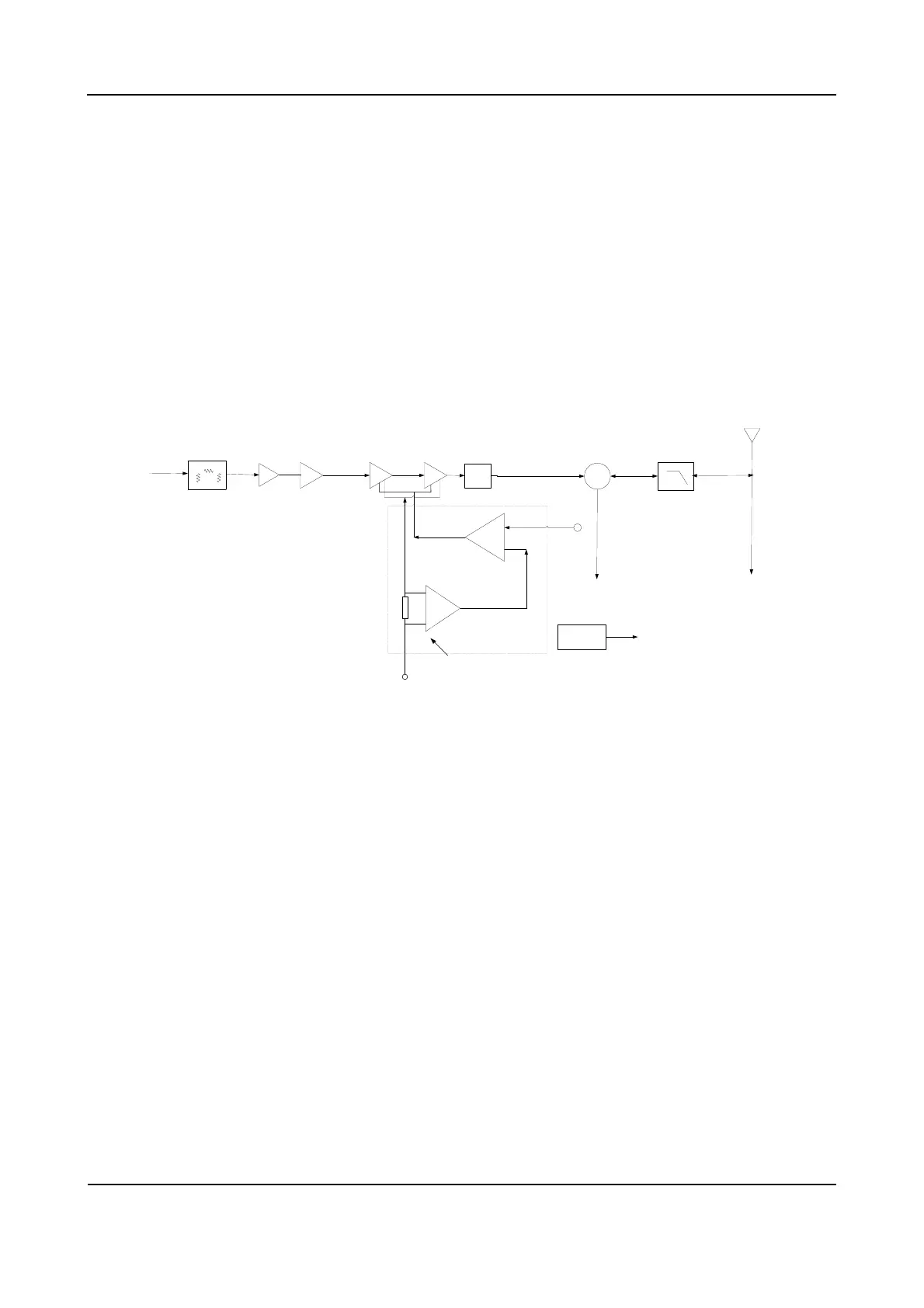
9.1 Transmitter Circuit
The transmitter circuit is mainly composed of:
RF power amplifier circuit
Low-pass filter circuit (for suppressing harmonics)
Auto power control circuit (APC) (including temperature detection circuit)
Pre-Driver2 Drive-stage Final-stage Tx/Rx Switch Low-pass Filter
ANT
Microstrip
Matcher
TV1/APC
To RX
Gate voltage control
Subtracter
FGU
Sampling resistor
BATT+
I/V convertor
APC module:
Pre-driver1
π
Attenuator
To GPS
TEM Sensor
Near To FinalPA
Tem Det Level
Figure 9-1 Diagram of Transmitter Circuit
9.1.1 RF Power Amplifier Circuit
The carrier signal generated by the TX VCO is modulated and amplified, and then feeds to the
transmitter circuit via the following steps.
Step 1 The signal passes through a π-type attenuator first, allowing interstage isolation between the
RF power amplifier circuit and TX VCO.
Step 2 The signal goes to a pre-driver amplifier (2SC3356) for pre-amplification, providing further
interstage isolation.
Step 3 The signal goes to another pre-driver amplifier (2SC4988) and a driver amplifier (RD01) for
adequate power amplification, so as to obtain further amplification in the final-stage amplifier
(RD07).
 Loading...