Interface Definition Service Manual
28
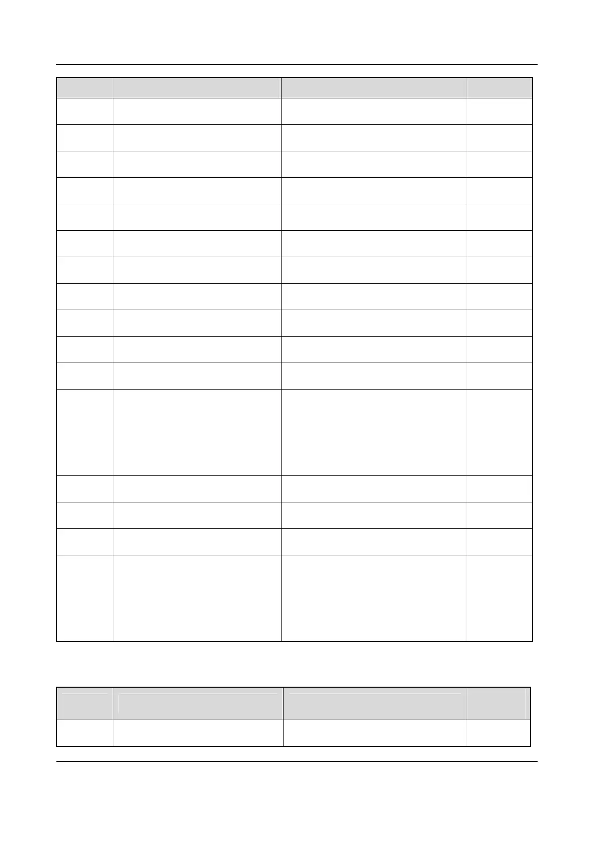
Pin No. Name Function Valid Level
1 Emergency Emergency L
2 CH2 Channel select /
3 CH8 Channel select /
4 VOL Volume adjust /
5 CH4 Channel select /
6 CH1 Channel select /
7 LED1 Red LED enable H
8 LED2 Green LED enable H
9 GND / /
10 INT-MIC+780 Microphone+ /
11 INT-MIC-780 Microphone- /
12 NC/GND NC for Version K of
UHF1/UHF2/UHF3, Version F of UHF5
and Version B of VHF
GND for Version F/H of UHF1
/
13 PWR-SW- Power-on enable input /
14 PWR-SW+ Power-on enable output /
15 3V3DRF 3.3V power supply /
16 NC/GND NC for Version K of
UHF1/UHF2/UHF3, Version F of UHF5
and Version B of VHF
GND (for Version F/H of UHF1)
/
Table 6-3 Definition of Channel Board Interface
J2: 20-Pin Option Board Interface
Pin No. Name Function
Valid
Level
1 IO1-OPT GPIO L/H
 Loading...