Service Manual UHF5 (806-941MHz) Information
301
10. UHF5 (806-941MHz) Information
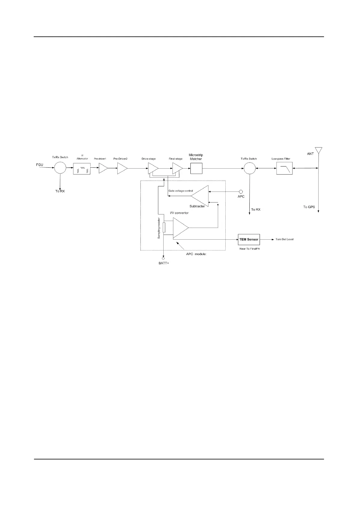
10.1 Transmitter Circuit
The transmitter circuit is mainly composed of:
RF power amplifier circuit
Low-pass filter circuit (for suppressing harmonics)
Auto power control circuit (APC) (including temperature detection circuit)
Figure 10-1 Diagram of Transmitter Circuit
10.1.1 RF Power Amplifier Circuit
The carrier signal generated by the high/low VCO is modulated and amplified, and then feeds to the
transmitter circuit via the following steps.
Step 1 The signal passes through a RX/TX switch (UPG2012TK), which switches the signal to the TX
channel.
Step 2 The signal passes through a π-type attenuator, allowing interstage isolation between the RF
power amplifier circuit and the VCO.
Step 3 The signal goes to a pre-driver amplifier (BFG425W) for pre-amplification, providing further
interstage isolation.
Step 4 The signal goes to another pre-driver amplifier (ADA4743) and a driver amplifier (RD01) for
adequate power amplification, so as to obtain further amplification in the final-stage amplifier
(RD07).
 Loading...