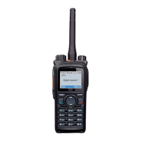
Service Manual UHF5 (806-941MHz) Information
393
Description of Normal Situations:
[1] Voltage of the power supply: about 7.4V.
[2] For low power, APC-OUT: 1.3-1.4V; for high power, APC-OUT: 1.5-1.8V.
[3] For low power, APC-IN: 1.2-1.3V; for high power, APC-IN: 1.5-1.7V.
[4] PS-APC: about 3.3V.
[5] TX5V: about 5V; RT5V: about 5V; PS-TX: about 3.3V.
[6] High power: about 2.5W; low power: about 1.2W.
[7] Start-up voltage of D9002: about 0.7V. The low-pass coil must be soldered appropriately and
remain in good condition. The spring plate for the antenna must well fit the antenna connector.
[8] The match components must not be soldered inappropriately or damaged.
[9] Vdd: about 7.3V; for low power, Vgg: 0.7-0.8V; for high power, Vgg: 0.85-1V.
[10] Vdd: about 7.3V; for low power, Vgg: 1.3-1.4V; for high power, Vgg: 1.5-1.7V.
[11] U107 PIN1: about 1.7V; U107 PIN3: about 3.3V.
[12] For Q9011, Vb: about 0.8V, Vc: about 2.7V; for U1004, Vdd: about 3.3V, Vcont: 0V (during
transmission).
Note
The above check operations should be made under 7.4V voltage.

 Loading...