13
7.1.2 Using the Mounting Holes on Top of the Base (SA5C, SA6C, SA7C)
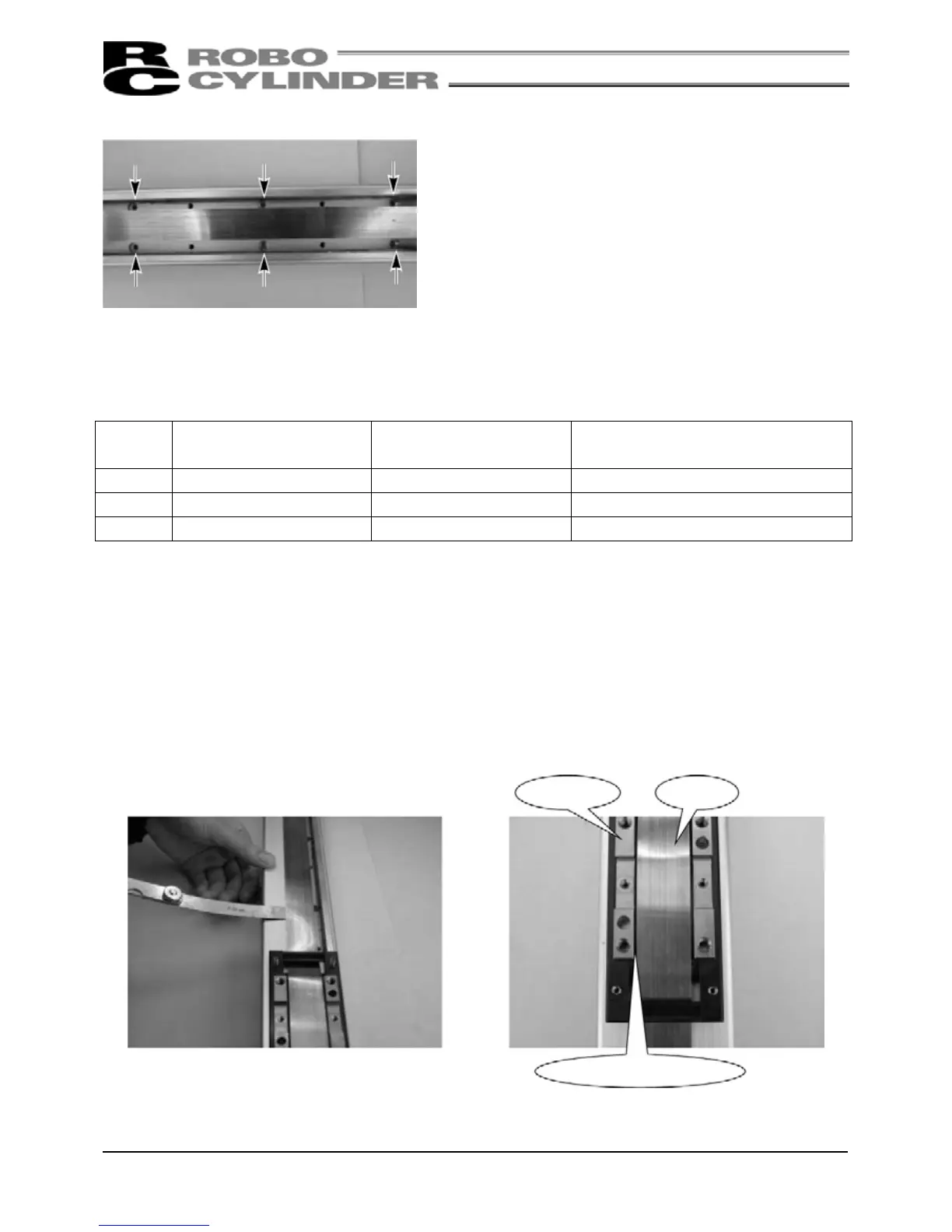
Through holes are provided in the base for installing the
actuator on its top face.
When installing the actuator, remove the side covers.
(Remove the two thin-head screws [M3 x 6mm] for mounting
the cover using an Allen wrench of 1. 5mm across flats.)
When securing with bolts, protect the stainless sheet from
dents or damage by making sure not to drop bolts or tools
onto the stainless sheet or contact them with it.
As for mounting bolts, use hexagon socket-head bolts conforming to the applicable specification in the table
below in accordance with the machine frame material.
Type
When the mating material
is steel
When the mating material
is aluminum
Mounting Hole (Reference)
SA5C M4 × 10 M4 × 15 φ4.5 drill, φ8 counterbore depth 4.5
SA6C M4 × 10 M4 × 15 φ4.5 drill, φ8 counterbore depth 4.5
SA7C M5 × 10 M4 × 15 φ6 drill, φ9.5 counterbore depth 5.5
(Note) When reinstalling the side covers, do not let them contact the end faces of the stainless sheet. This
may damage or bend the stainless sheet, causing the sheet to deteriorate or wear quickly.
Therefore, install the side covers and check for bending according to the procedure below.
(1) To prevent the side covers from contacting
the end faces of the sheet, insert a shim
(approx. 0.1 to 0.2mm) between the sheet
and each cover to provide a slight allowance,
and gently push in the cover.
(2) Remove the slider covers and check to see
that the right and left clearances between the
slider and sheet are nearly equal and no
bending is created.
(3) Finally, move the slider back and forth several times along the entire stroke to check that the slider does not
contact the sheet.