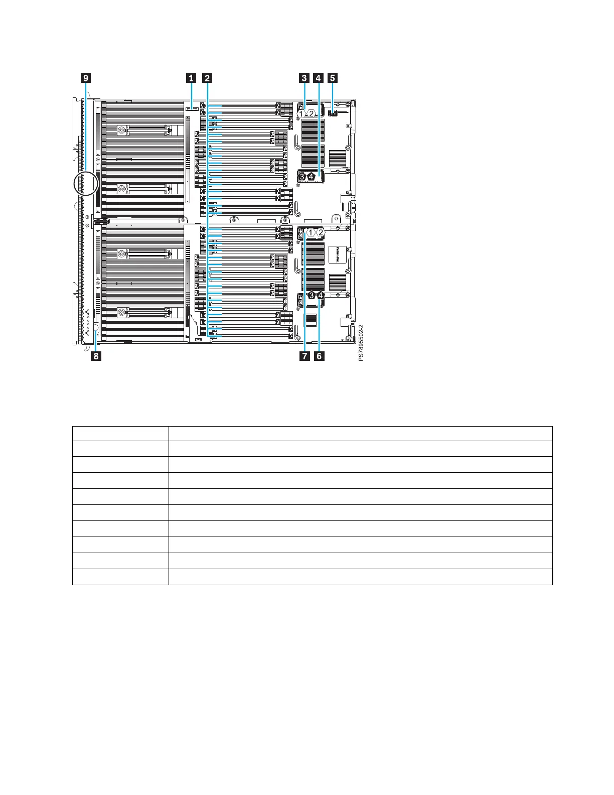
The following table identifies and describes the connectors for the IBM Flex System p460 Compute Node.
Table 3. Connectors for the IBM Flex System p460 Compute Node
Callout IBM Flex System p460 Compute Node connectors
▌1▐ 3 V lithium battery connector (P1-E1)
▌2▐ DIMM connectors (See Figure 5 on page 16 for individual connectors.)
▌3▐ I/O expansion card M1 connector for chassis bays 1 and 2 (P1-C34)
▌4▐ I/O expansion card M2 connector for chassis bays 3 and 4 (P1-C35)
▌5▐ Management card connector (P1-C38)
▌6▐ I/O expansion card M4 connector for chassis bays 3 and 4 (P1-C37)
▌7▐ I/O expansion card M3 connector for chassis bays 1 and 2 (P1-C36)
▌8▐ Light path card
▌9▐ Thermal sensor
The following figure shows individual DIMM connectors for the IBM Flex System p260 Compute Node
system board.
Figure 3. Base-unit connectors for the IBM Flex System p460 Compute Node
Chapter 2. Power, controls, indicators, and connectors 15