System-board connectors
Compute node components attach to the connectors on the system board.
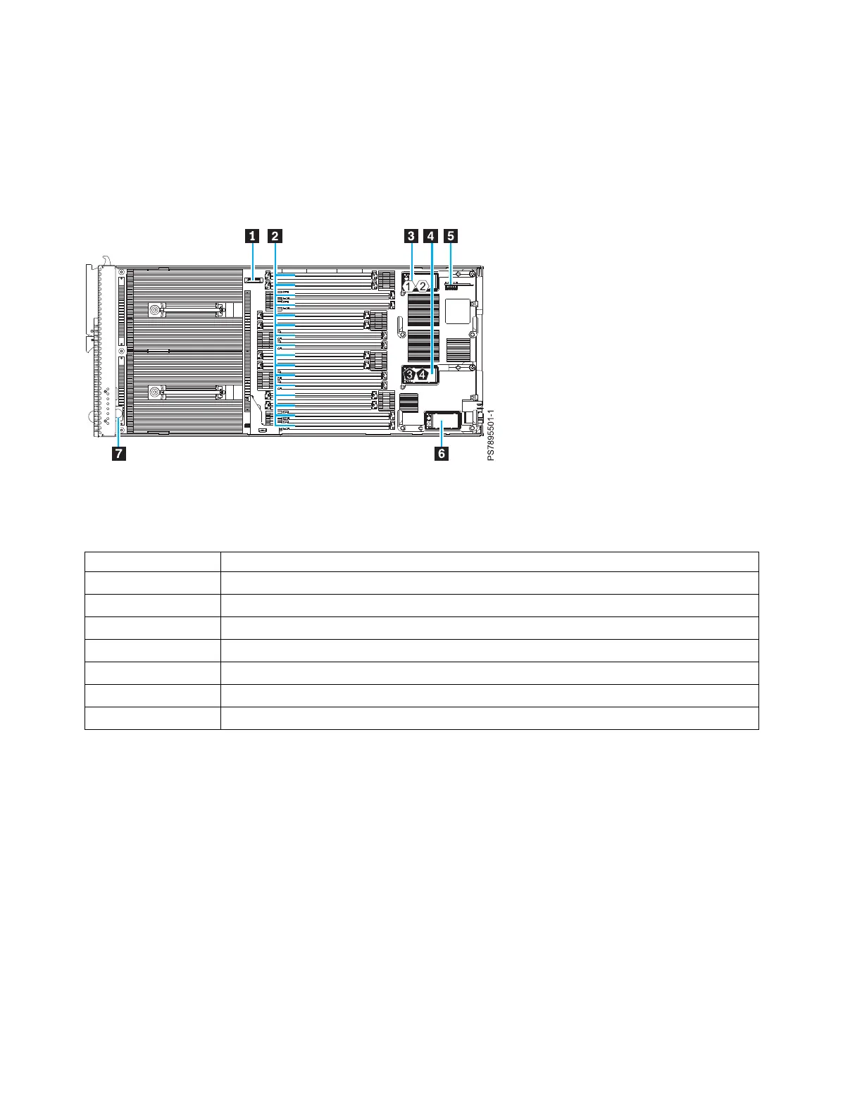
The following figure shows the connectors on the base-unit system board in the IBM Flex System p260
Compute Node.
The following table identifies and describes the connectors for the IBM Flex System p260 Compute Node.
Table 2. Connectors for the IBM Flex System p260 Compute Node
Callout IBM Flex System p260 Compute Node connectors
▌1▐ 3 V lithium battery connector (P1-E1)
▌2▐ DIMM connectors (See Figure 4 on page 16 for individual connectors.)
▌3▐ I/O expansion card top connector for chassis bays 1 and 2 (P1-C18)
▌4▐ I/O expansion card bottom connector for chassis bays 3 and 4 (P1-C19)
▌5▐ Management card connector (P1-C21)
▌6▐ Everything-to-Everywhere (ETE) connector (P1-C20)
▌7▐ Light path card
The following figure shows the connectors on the base-unit system board in the IBM Flex System p460
Compute Node.
Figure 2. System-board connectors for the IBM Flex System p260 Compute Node
14 Power Systems: IBM Flex System p260 and p460 Compute Nodes Installation and Service Guide