EasyManuals Logo

IBM Flex System V7000 User Manual

IBM Flex System V7000
192 pages
To Next Page IconTo Next Page
To Previous Page IconTo Previous Page
Page #119 background imageLoading...
Page #119 background image
Chapter 3. Systems management 101
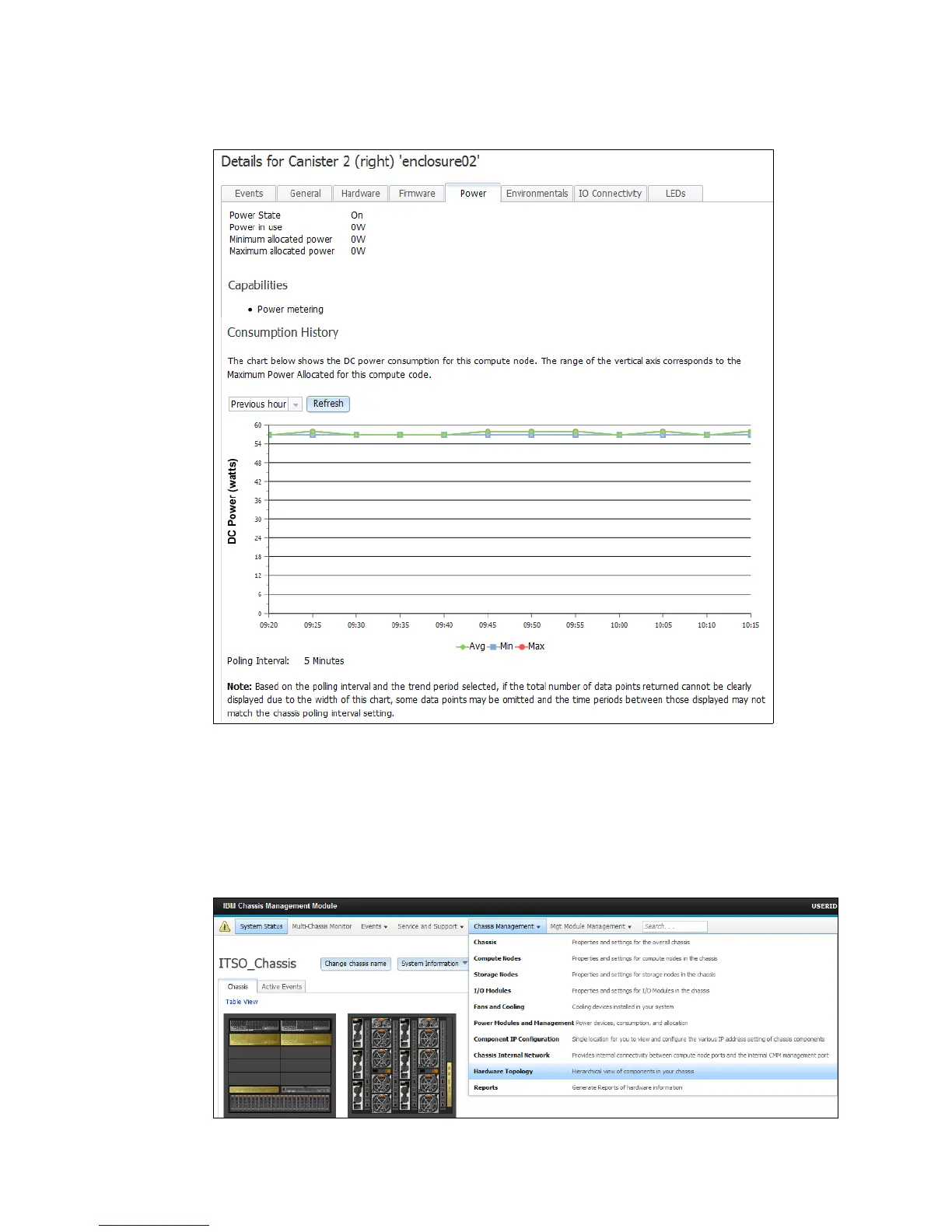
Figure 3-24 shows the DC Power consumption for the component.
Figure 3-24 Power consumption of selected chassis component
The IBM Flex System Chassis Management Module web interface has a menu structure at
the top of each page that gives easy access to most management functions. One of the most
frequently used menu items, Chassis Management, shows properties, settings, and various
views and reports regarding the nodes, modules, and other components in the chassis.
Figure 3-25 shows the option that gives the hierarchical view of chassis components.
Figure 3-25 Hardware Topology view from Chassis Management menu

Table of Contents

Other manuals for IBM Flex System V7000

Questions and Answers:

Question and Answer IconNeed help?

Do you have a question about the IBM Flex System V7000 and is the answer not in the manual?

IBM Flex System V7000 Specifications

General IconGeneral
Form Factor2U
ModelIBM Flex System V7000
CategoryStorage
Power SupplyDual redundant power supplies
Storage ControllerDual active-active controllers
RAID LevelsRAID 0, 1, 5, 6, 10
Maximum Drives240
Expansion EnclosuresUp to 9
Drive Types SupportedSSD, HDD
Host Interface Ports8 Gbps FC
ScalabilityScalable with expansion enclosures
Operating Temperature5°C to 40°C
Management InterfaceWeb-based GUI, CLI, SMI-S

Related product manuals