48 IBM Flex System V7000 Storage Node Introduction and Implementation Guide
The Flex System V7000 Storage Node has two available slots in each control canister for
populating with host network adapters. The adapters in each of the node canisters must be of
the same type in each of the slots; so the adapters are installed in pairs (one adapter per
node canister) and the following adapter configurations are supported for the entire Flex
System V7000 Storage Node:
Two or four 10 Gb CNA network adapters
Two 4-port 8 Gb FC network adapters
Two 10 Gb CNA network adapters and two 4-port 8 Gb FC network adapters
The 2-port 10 Gb Ethernet network adapters (up to two per canister) are used for iSCSI host
attachment and/or FCoE attachment.
The configuration of the host attachments on one control canister must match the
configuration of the second.
There is a 6 Gbps SAS port on the front of the canister for connecting optional expansions
enclosures.
2.4.1 Control canister
The control canister is responsible for the management of all the virtualization, RAID
functions, advanced features and functions of the IBM Flex System V7000 Storage Node and
all command and I/O to its internal drive slots and the expansions that it is connected to. The
control canister is a Customer Replaceable Unit (CRU). Figure 2-3 is a picture of the control
canister with its cover removed.
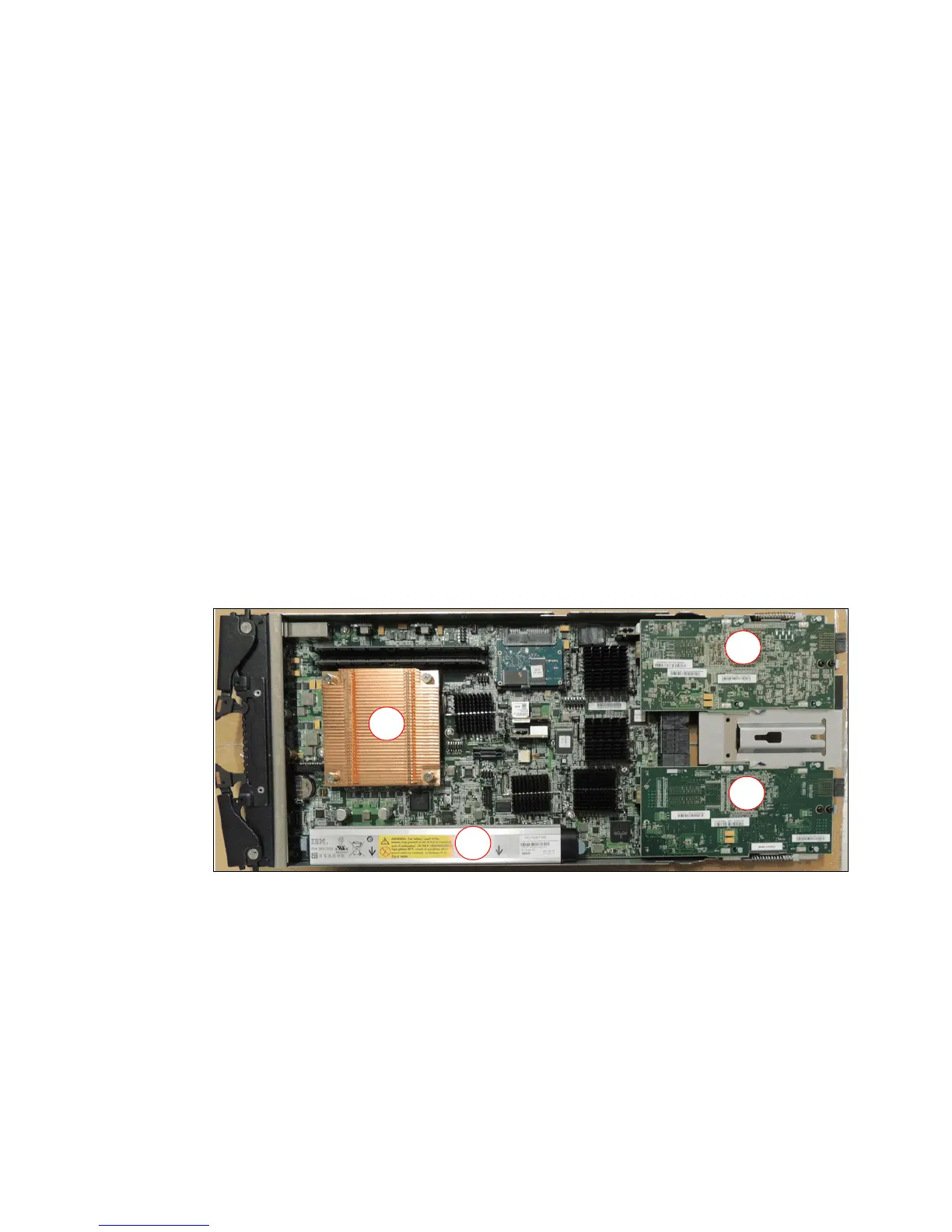
Figure 2-3 Components and board layout of the control canister
In Figure 2-3, the processor (A) is a quad core Jasper. There are also two DIMMs which make
up the cache memory and the battery backup unit (B) which beside the control canister is also
a Customer Replaceable Unit (CRU).
As described before, the two host network adapter card locations (C and D) can also be seen.
These provide the connections to the Flex System Enterprise Chassis through the midplane
and the switch modules. It is important to remember that both control canisters must be
populated with the same type of host network adapter cards in each of these locations.