Chapter 1. Introduction to IBM Flex Systems and IBM PureSystems offerings 25
If a node has a two port integrated LAN on Motherboard (LOM) as standard, Module 1 and 2
are connected to it. If an I/O adapter is installed in the nodes I/O expansion bay 1, then
Module 1 and 2 would be connected to this. Module 3 and 4 connect to the I/O adapter that is
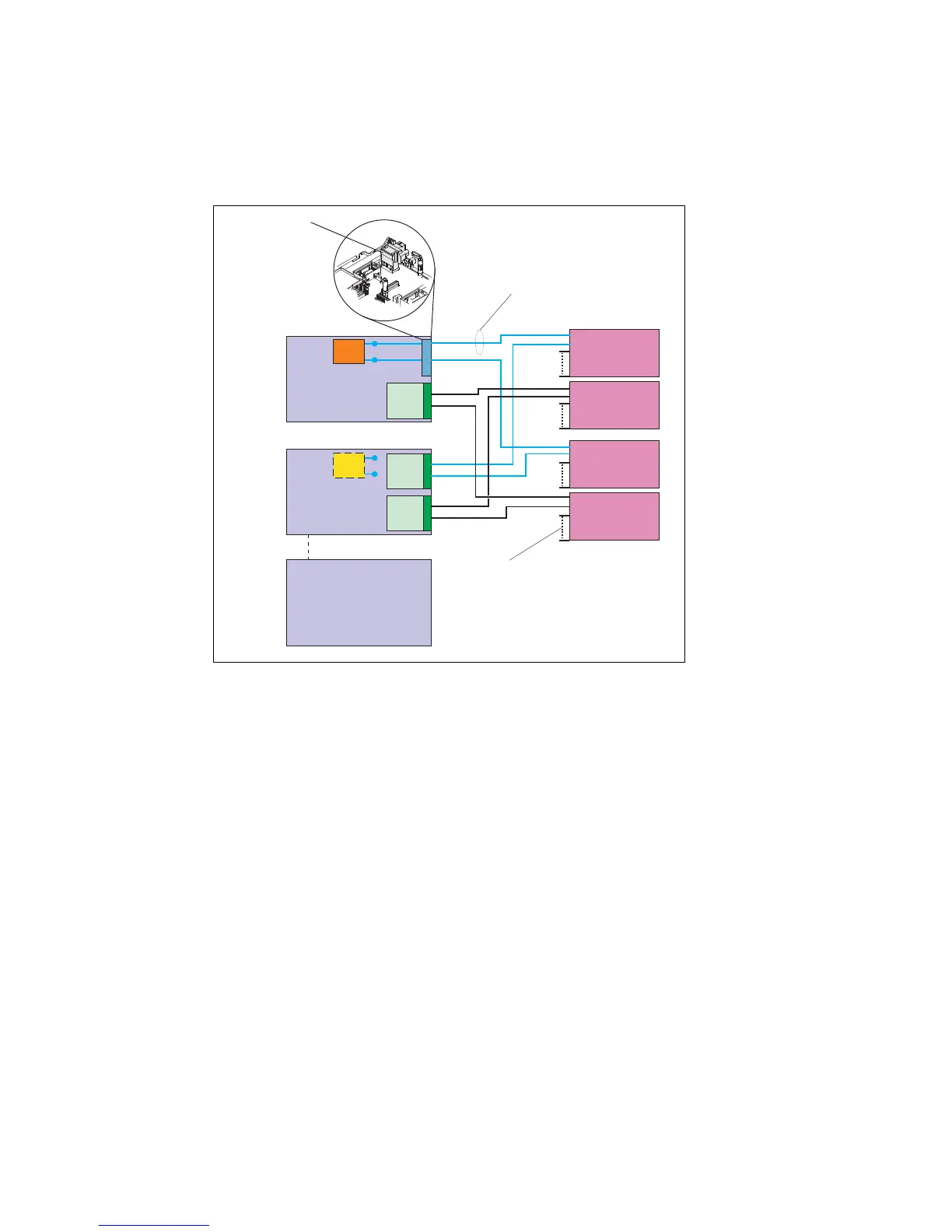
installed within I/O expansion bay 2 on the node. See Figure 1-14.
Figure 1-14 LOM, I/O adapter and switch module connection for node bays
The node in Bay 1 in Figure 1-14 shows that when shipped with a LOM, the LOM connector
provides the link from the node motherboard to the midplane. Some nodes do not ship with
LOM.
If required, this LOM connector can be removed and an I/O expansion adapter installed in its
place. It is shown on the node in Bay 2 in Figure 1-14.
1.5.1 IBM Flex System Fabric CN4093 10 Gb Converged Scalable Switch
The IBM Flex System Fabric CN4093 10 Gb Converged Scalable Switch provides support for
L2 and L3 switching, Converged Enhanced Ethernet (PFC, ETS, DCBX), Fibre Channel over
Ethernet (FCoE), NPV Gateway, and Full Fabric Fibre Channel Forwarder (FCF).
The switch has the following major components:
42 10 Gb Ethernet internal ports and twenty-two external ports. External ports are
arranged as two (small form-factor pluggable plus) SFP+ ports
12 SFP+ Omni Ports
2 Quad Small Form-Factor Pluggable Plus (QSFP+) ports.
Each Omni Port is capable of running in 10 Gb Ethernet or 4/8 Gb FC mode with
auto-negotiation capability.
Node
bay 1
with LOM
Node
bay 2
with I/O
expansion
adapter
Node
bay 14
LOM
LOM connector
(remove when
I/O expansion
adapter is installed)
I/O module 1
I/O module 3
I/O module 2
I/O module 4
LOM
4 lanes (KX-4) or
4 10 Gbps lanes (KR)
14 internal groups
(of 4 lanes each),
one to each node.