Chapter 2. Introduction to IBM Flex System V7000 Storage Node 49
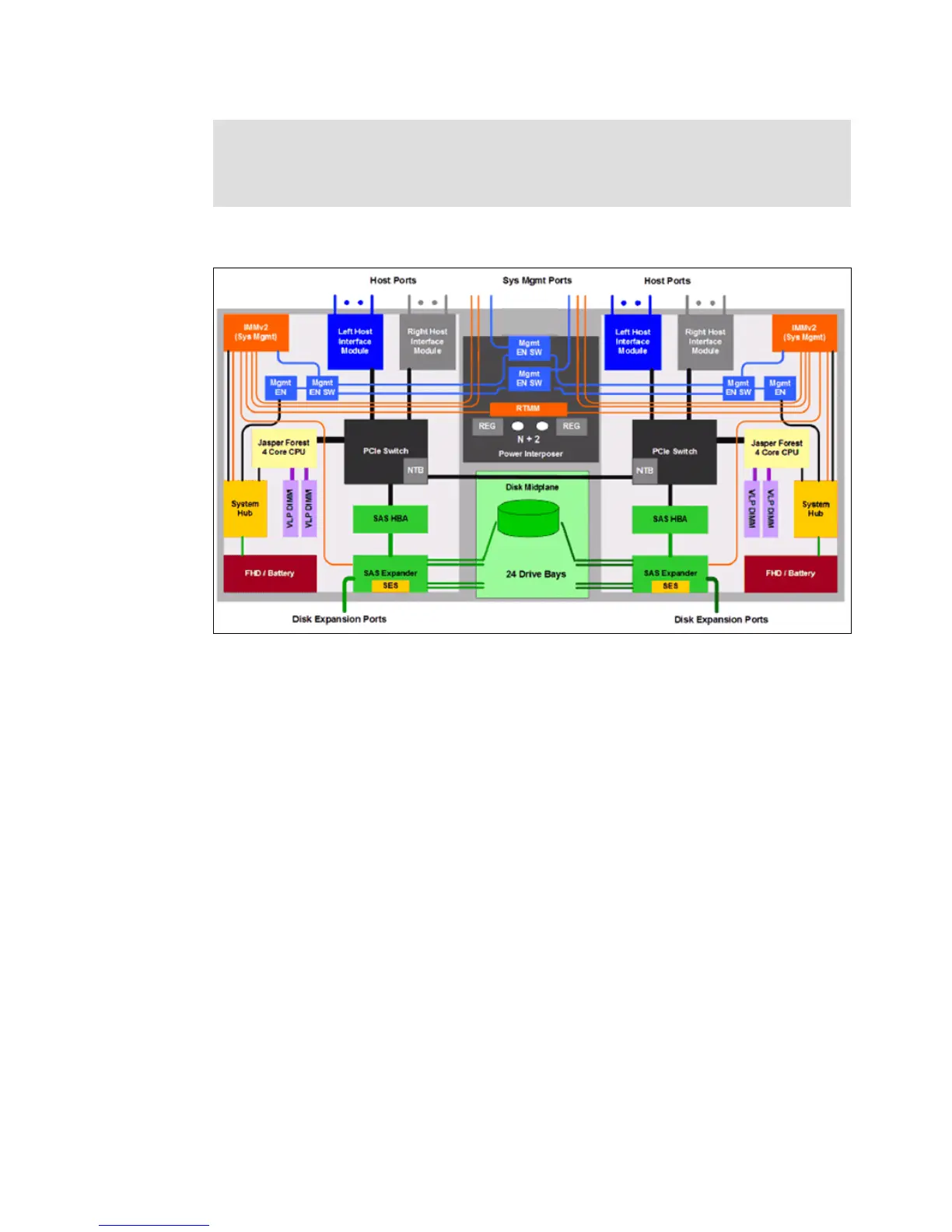
Figure 2-4 is a logical block diagram of the components and flow of the control canister.
Figure 2-4 Logical block diagram for control canister
Adapter locations: The first network adapter (slot1) location can only be populated by a
2-port 10 Gbps Ethernet CNA network adapter. The second location can be populated by
either a 2-port 10 Gbps Ethernet CNA network adapter or a 4 port 8 Gbps Fibre Channel
network adapter.