Options applicable to control enclosures
__ v Cache memory upgrade
__ v Four-port 8 Gbps Fibre Channel host interface adapter with two small
form-factor pluggable (SFP) transceivers installed
__ v Two extra Fibre Channel SFP transceivers
__ v Fibre Channel cables
__ v SAS cables
__ v Four-port 1 Gbps iSCSI host interface adapter
__ v Two-port 10 Gbps iSCSI / FCoE host interface adapter
__ v Drives
__ v Power cords for connection to wall sockets
Options applicable to expansion enclosures
__ v Expansion enclosure attachment cables
__ v Drives
__ v Power cords for connection to wall sockets
Identify the hardware components
The following graphics identify the hardware components and port locations for
the control enclosure and expansion enclosure on Storwize V3700 systems.
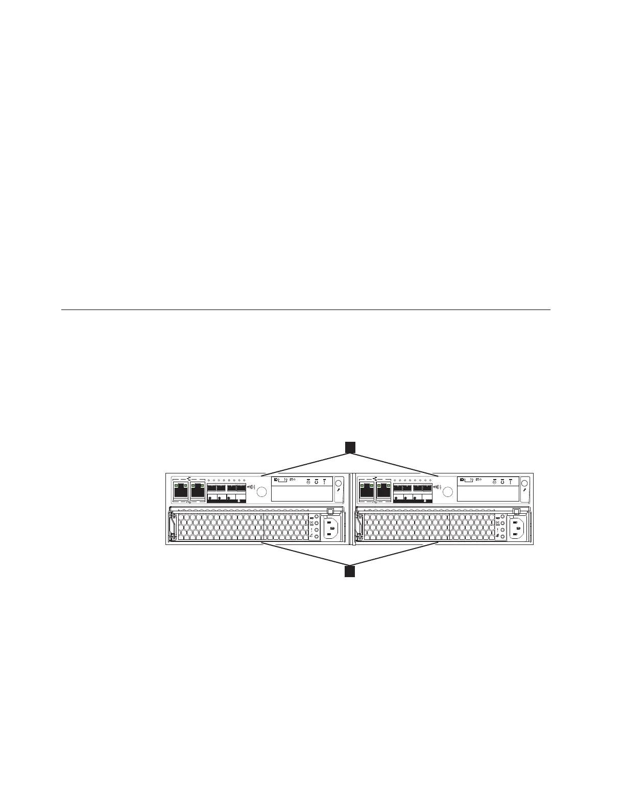
Control enclosure components
Figure 1 shows the rear view of a control enclosure and identifies the location of
the power supply units and node canisters.
Note: Figure 1 and Figure 2 on page 7 show an enclosure that is equipped with
alternating current (AC) power supplies. Some enclosure enclosure models have
direct current (DC) power supplies instead (see “Reviewing your packing slip” on
page 5 for the model numbers). For more information about DC power supply
units, see “Direct current power supply units” on page 10.
Note: Figure 1 shows the node canisters in their initial configuration, with no host
interface adapter options installed.
Data ports
v3500112
1
2
1
2
1
2
OK
IN
1 2 3
4
6
1
2
1
2
OK
IN
1 2 3
4
6
Figure 1. Rear view of a Storwize V3700 control enclosure
6 Storwize V3700: Quick Installation Guide

 Loading...


