7. Remove the microprocessor heat-exchanger assembly and microprocessor;
then, place them on a static-protective surface for reinstallation (see
“Removing the microprocessor” on page 99).
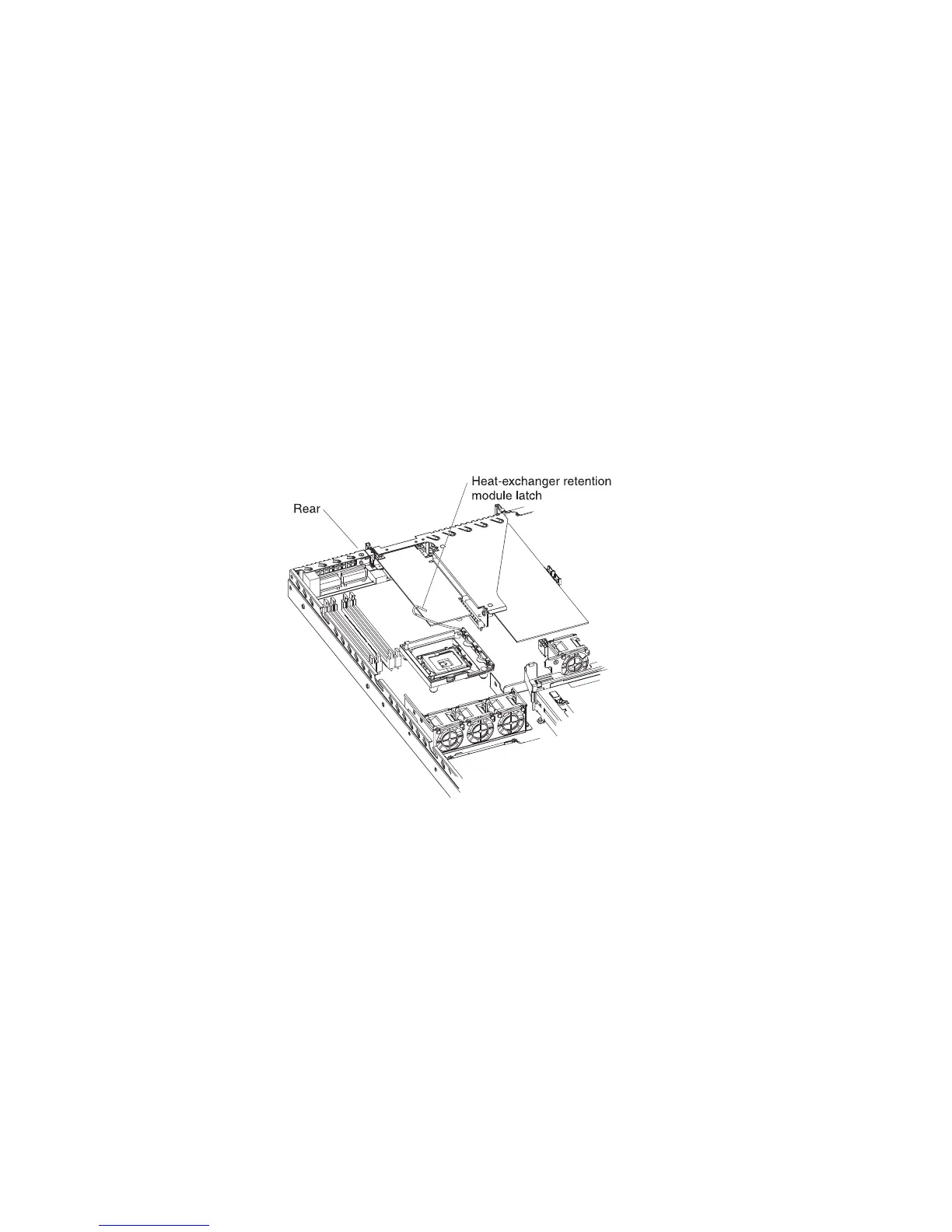
8. Note the orientation of the microprocessor retention module.
9. Remove the four screws that hold the microprocessor retention module to the
system board; then, lift the retention module out of the server.
10. Remove the remaining eight screws that secure the system board to the
chassis, and put the screws in a safe place.
11. Lift the system board out of the server.
Installing the system board
Note: When you reassemble the components in the server, be sure to route all
cables carefully so that they are not exposed to excessive pressure.
To reinstall the system board, complete the following steps:
1. Align the system board with the chassis, and replace the eight screws that you
removed in step 10 of “Removing the system board” on page 103.
2. Orient the microprocessor retention module as shown in the illustration.
3. Replace the microprocessor retention module. Secure it with the four screws
that you removed in step 9 of “Removing the system board” on page 103.
4. Replace the microprocessor and microprocessor heat-exchanger assembly
(see “Installing the microprocessor” on page 100).
5. Reconnect to the system board the cables that you disconnected in step 6 of
“Removing the system board” on page 103.
6. Replace the SAS/SATA controller if you removed one (see “Installing the
SAS/SATA controller (hot-swap models)” on page 94).
7. Replace the DIMMs (see “Installing a memory module (DIMM)” on page 79).
8. Replace the riser-card assembly and adapters.
9. Replace the server cover (see “Installing the cover” on page 69).
10. Slide the server into the rack.
11. Connect all external cables and the power cord; then, turn on the server.
104 IBM System x3250 Types 4364 and 4365: Problem Determination and Service Guide
 Loading...


