System-board switches and jumpers
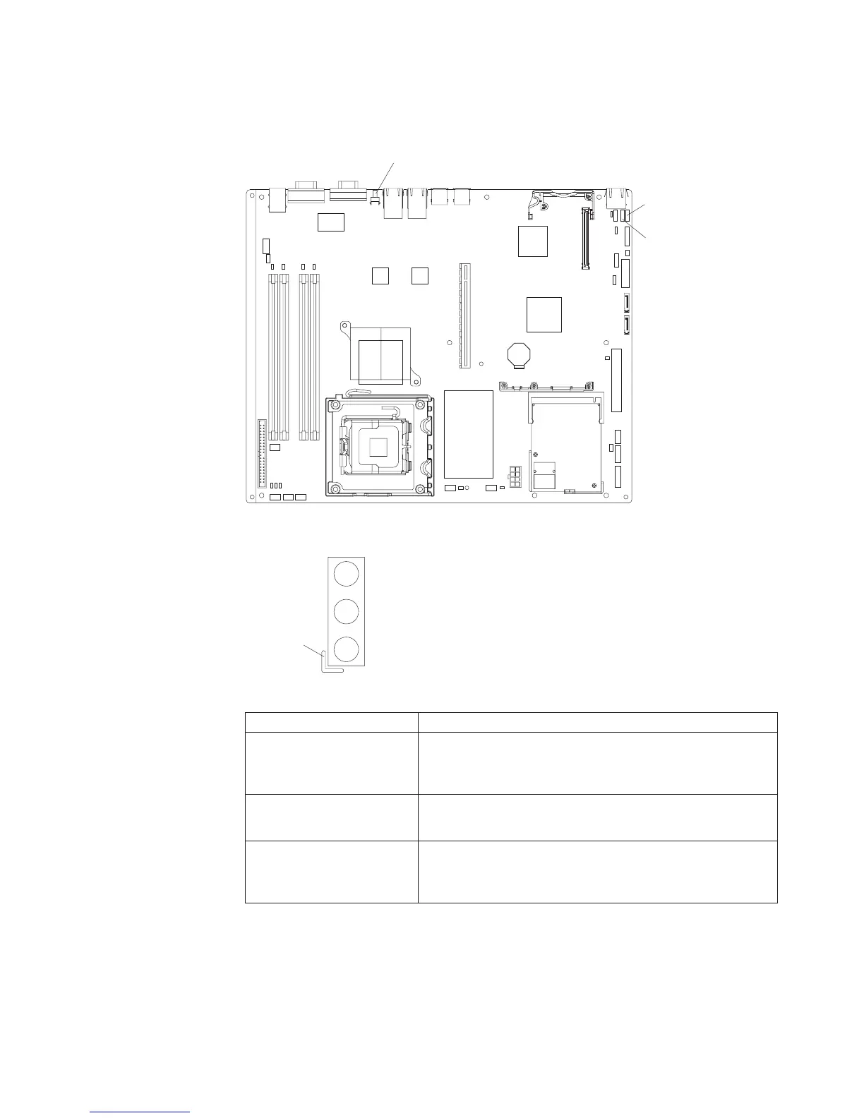
The following illustration shows the switches and jumpers on the system board.
Boot block
recovery jumper
Clear CMOS jumper
NMI switch
The following illustration identifies the pins on a jumper and shows the location of
pin 1.
3
2
1
Pin 1 mark
Table 2. Switch and jumper settings
Component Settings
CMOS jumper (JP3)
v Pins 1 and 2: Keep CMOS data (default)
v Pins 2 and 3: Clear the CMOS data, which clears the
power-on password and administrator password
Boot block jumper (JP4)
v Pins 1 and 2: Normal (default)
v Pins 2 and 3: Recover boot block
NMI (non-maskable
interrupt) switch (SW1)
v Normal (default): No NMI issued
v The NMI button that is on the rear of server, connected to
this switch, has been pressed: NMI issued
Chapter 1. Introduction 7

 Loading...


