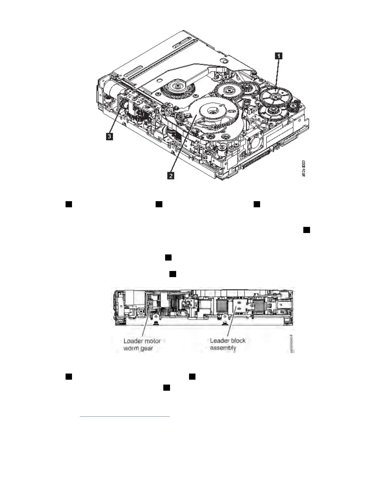
Figure 130. Drive with cover removed to reveal gear train.
1 Threader
intermediate gear
2 Threader mechanism gear 3 Loader motor worm
gear
5. As the leader pin is secured in the cartridge, you hear the leader pin retention spring clips click into
place. If you do not hear the click, continue rolling until the threader intermediate gear (1) stops. The
LBA is in the correct position.
Note: Be sure to keep tension on the tape as the LBA is drawn into the cartridge.
6. Rotate the loader intermediate gear (1) clockwise as viewed from the front of the drive until it stops.
This action releases the LBA leader pin.
7. Rotate the threader motor worm gear (3) counterclockwise until the leader block is in front of the
read/write head. This action moves the LBA out of the cartridge.
Figure 131. Leader Block Assembly (LBA)
1 Loader motor worm gear 2 Leader block assembly (LBA)
8. Rotate the loader motor worm gear (3) counterclockwise as viewed from the front of the drive until it
stops.
9. Remove the cartridge from the cartridge loader tray.
10. Go to “Ending procedure” on page 220.
IBM Condential
Appendix I. Manual cartridge removal procedure219
 Loading...


