EasyManuals Logo

IBM x3550 M4 Type 7914 User Manual

IBM x3550 M4 Type 7914
868 pages
To Next Page IconTo Next Page
To Previous Page IconTo Previous Page
Page #327 background imageLoading...
Page #327 background image
Replacing the operator information panel assembly
Use this information to replace the operator information panel assembly.
About this task
To install the operator information panel, complete the following steps.
Procedure
1. Read the safety information that begins on “Safety” on page vii and
“Installation guidelines” on page 33.
2. Turn off the server and peripheral devices and disconnect the power cords and
all external cables, if necessary.
3. Remove the cover (see “Removing the cover” on page 36).
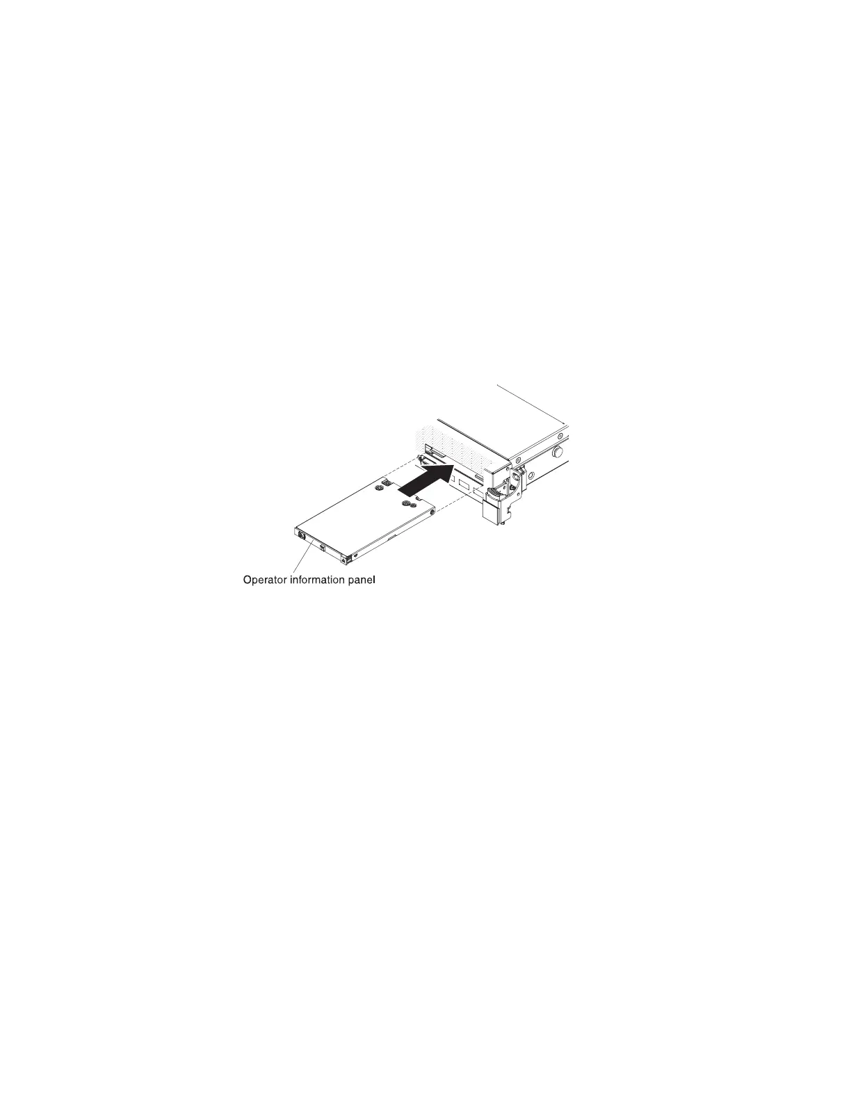
4. From the front of the server, slide the operator information panel into the
server until it clicks into place.
5. Inside the server, connect the cable to the rear of the operator information panel
assembly. The following illustration shows the cable routing for the operator
information panel.
Figure 211. Operator information panel installation
Chapter 6. Removing and replacing components 309

Table of Contents

Questions and Answers:

Question and Answer IconNeed help?

Do you have a question about the IBM x3550 M4 Type 7914 and is the answer not in the manual?

IBM x3550 M4 Type 7914 Specifications

General IconGeneral
Form Factor1U Rack
Memory Slots24 DIMM slots
Operating System SupportMicrosoft Windows Server, Red Hat Enterprise Linux, SUSE Linux Enterprise Server, VMware vSphere
ProcessorUp to two Intel Xeon E5-2600 or E5-2600 v2 series processors
ChipsetIntel C600 Series Chipset
MemoryUp to 768GB DDR3
RAID SupportRAID 0, 1, 10
Network Interface4 x 1GbE (embedded)
Power SupplyDual hot-swap power supplies (550W, 750W, or 900W)
Expansion SlotsUp to 3 PCIe 3.0 slots
StorageUp to 8 x 2.5" or 4 x 3.5" hot-swap drives

Related product manuals