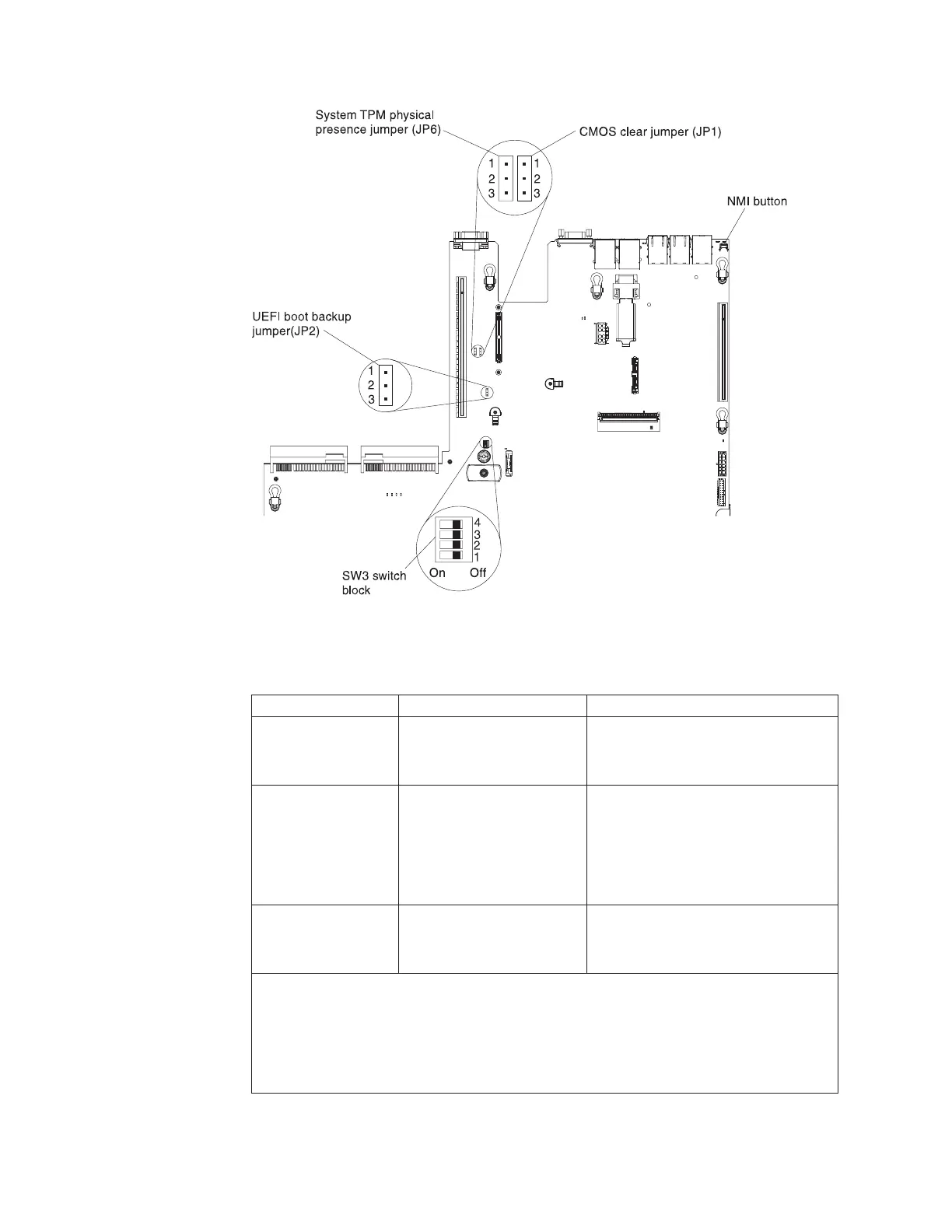
The following table describes the jumpers on the system board.
Table 2. System board jumpers
Jumper number Jumper name Jumper setting
JP1 CMOS clear jumper
v Pins 1 and 2: Normal (default).
v Pins 2 and 3: Clears the real-time
clock (RTC) registry.
JP2 UEFI boot backup jumper
v Pins 1 and 2: Normal (default).
Loads the primary server firmware
ROM page.
v Pins 2 and 3: Loads the secondary
(backup) server firmware ROM
page.
JP6 System TPM physical
presence jumper
v Pins 1 and 2: Normal (default).
v Pins 2 and 3: Indicates a physical
presence to the system TPM.
Notes:
1. If no jumper is present, the server responds as if the pins are set to the default.
2. Changing the position of the UEFI boot backup jumper (JP2) from pins 1 and 2 to pins
2 and 3 before the server is turned on alters which flash ROM page is loaded. Do not
change the jumper pin position after the server is turned on. This can cause an
unpredictable problem.
Figure 17. System-board switches, jumpers, and buttons
30 IBM System x3550 M4 Type 7914: Installation and Service Guide
 Loading...


