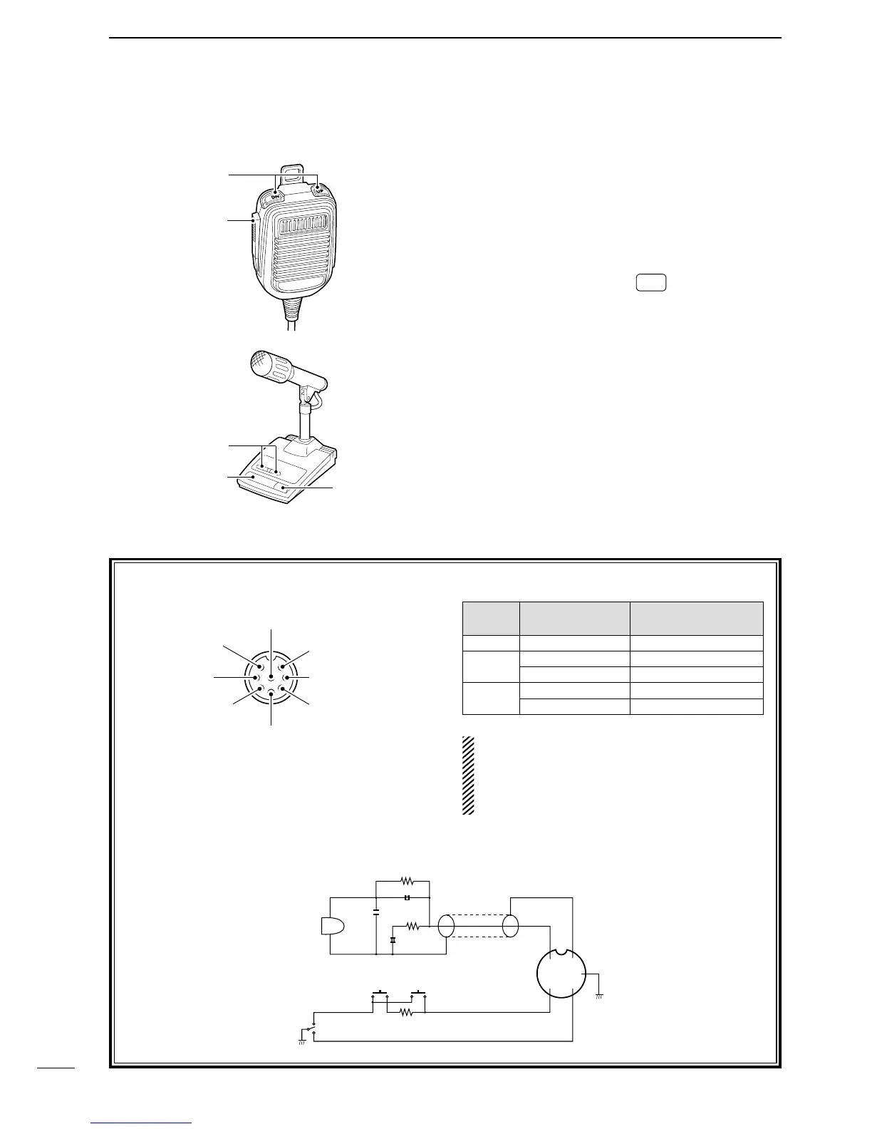
[MIC]
PIN NO.
FUNCTION DESCRIPTION
w
+8 V DC output Max. 10 mA
e
Frequency up Ground
Frequency down Ground through 470 ˘
r
Squelch open “LOW” level
Squelch close “HIGH” level
CAUTION: DO NOT short pin 2 to ground as
this can damage the internal 8 V regulator. DC
voltage is applied to pin 1 for microphone opera-
tion. Use caution when using a non-Icom micro-
phone.
• HM-36 SCHEMATIC DIAGRAM
q UP/DOWN SWITCHES [UP]/[DN]
Change the selected readout frequency or memory
channel.
• Pushing the switch continuously changes the frequency
or memory channel number continuously.
• The [UP]/[DN] switch can simulate a key paddle. Select
in set mode (U/D KEY; Mic Up/Down Keyer). (p. 80)
• While pushing and holding
RIT
*, push the [UP]/[DN]
switch to control the transmit readout frequency while
in spilt frequency operation.
* Available only when the XFC (transmit frequency
check) function is turned ON. (p. 76)
w PTT SWITCH
Push and hold to transmit; release to receive.
e PTT LOCK SWITCH (SM-20 only)
Push to lock the PTT switch to the transmission
codition.

 Loading...


