1
PANEL DESCRIPTION
1-5
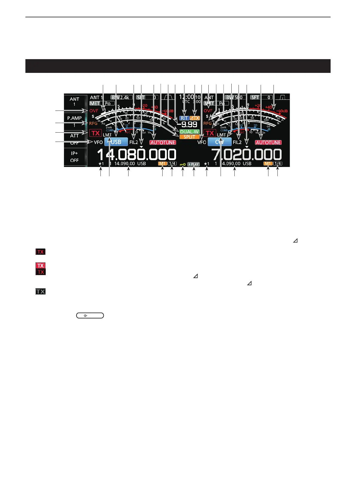
@1 VFO/MEMORY ICON (p. 3-1)
“VFO”isdisplayedwhentheVFOmodeisselected,
and the memory number is displayed when a
Memory channel is selected.
@2 TX STATUS INDICATOR (p. 3-4, 3-9)
Displays the transmit status of the displayed
frequency.
• isdisplayedwhilethedisplayedfrequencyiswithin
the amateur band range.
•
(Red background) is displayed while transmitting.
•
(With a border of short dashes) is displayed when
theselectedfrequencyisoutsideoftheamateurband
frequency.
• (Grayed out) is displayed while the transmitter is
inhibited.
@3 RF GAIN INDICATOR (p. 3-7)
Displayed when
(outer) is set
counterclockwise from the 11 o’clock position. The
indicator shows that the RF gain is reduced.
@4 OVF ICON (p. 3-7)
“OVF”isdisplayedwhenanexcessivelystrong
signal is received.
@5 METER INDICATOR (p. 3-7)
DisplaystheS,I
d,Po,SWR,COMP,ALCandVd
meters.
@6 MODE INDICATOR (p. 3-3)
Displays the selected operating mode.
@7 IF FILTER INDICATOR (p. 4-3, 4-4)
DisplaystheselectedIFlter.
@8 QUICK TUNING ICON (p. 3-4)
DisplayedwhenthequickTuningStepfunctionis
ON.
@9 AUTO TUNE INDICATOR (p. 4-8)
Displays“AUTOTUNE”whentheAutoTuning
function is ON.
Touch screen display (Continued)
#0 SPLIT ICON (p. 4-9)
Displayed when the Split function is ON.
#1 DUALWATCH ICON (p. 3-2)
Displayed when using Dualwatch.
#2 SHIFT FREQUENCY READOUT (p. 4-1)
Displays the shift offset for the RIT or
TX
functions,whilethesefunctionsareON.
#3 RIT ICON (p. 4-1)
Displayed when the RIT function is ON.
#4
TX ICON
Displayed when the TX function is ON.
#5 1/4 TUNING STEP INDICATOR (p. 3-5)
Displayedwhilethe1/4TuningStepfunctionisON.
#6 M1~M8/T1~T8
• Displays“M1”~“M8”whileusingtheMemoryKeyer
function is used.
• Displays“T1”~“T8”whileusingtheVoiceTXmemory
function.
#7 MEMORY CHANNEL/VFO READOUT (p. 3-1)
Displays the selected memory channel contents in
theVFOmode,anddisplaystheVFOcontentsin
the Memory mode.
#8 LMT ICON
Displayedifthepowerampliertemperature
becomesextremelyhighandtheprotectionfunction
is activated after transmitting continuously for long
periods of time.
#9 SELECT MEMORY CHANNEL ICON
Indicates that the displayed memory channel is
assigned as a Select memory channel (★1~★3).
$0 PLAY ICON
Displayed while playing the recorded voice audio.
$1 DIAL LOCK INDICATOR (p. 3-6)
Displayed while the Lock function is ON.
@6 @7 @7@9 @9@8 @8
#5#5 #6#7$0$1#7 #9 #8#8#9 #6
#3 #4 @1@5 @4 @5
@2
@1
@3
@4
#0 #1 @2@3#2 @6

 Loading...


