18
5
SCAN OPERATION
■ Scan types
The IC-A14 has 3 scan types to suit your needs. IC-A14S
has 2 scan types.
■ COM band scan
q Push [CLR] to select the frequency mode.
w Push [SQLY]/[SQLZ] to set the squelch level to the point
where noise just disappears.
For the IC-A14
e Push [FUNC], then push [SCAN](2) to start the scan.
• When a signal is received, the scan pauses until the signal dis-
appears.
• To change the scanning direction, push [Y]/[Z].
For the IC-A14S
e Hold down [Y]/[Z] for 1 second to start the scan.
• When a signal is received, the scan pauses until the signal dis-
appears.
• To change the scanning direction, push [Y]/[Z].
r To stop the scan, push [CLR].
WEATHER CHANNEL SCAN
Repeatedly scans all “TAG” weather channels. Weather
channels are available for the IC-A14 only.
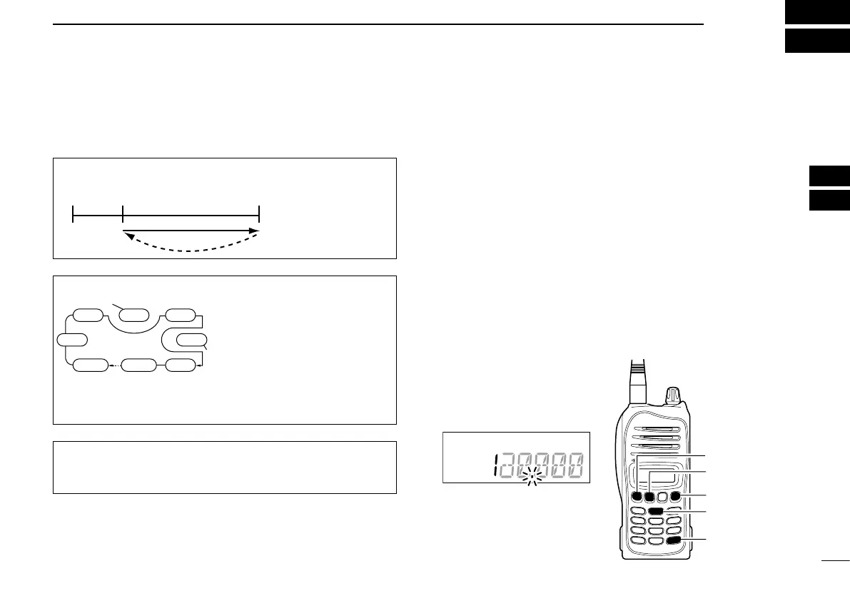
COM BAND SCAN
Repeatedly scans
all frequencies
over the entire
COM band.
MHz
Scan
Jump
MHz
MHz
MEMORY SCAN
Repeatedly scans se-
lected memory bank’s
all “TAG” memory chan-
nels. Used for checking
often-used channels and
bypassing usually busy
channels such as control-
tower frequencies.
non-TAG
channel
Mch 2 Mch 4 Mch 6
Mch 7Mch 1
Mch 8Mch 10Mch 19
Decimal point blinks during a
scan.
[FUNC]
[CLR]
[SCAN](2)
[Y]
[Z]
1
2
3
4
5
6
7
8
9
10
11
12
13
14
15
16
17
18
19

 Loading...