44
1
2
3
4
5
6
7
8
9
10
11
12
13
14
15
16
17
18
19
20
21
White title
9
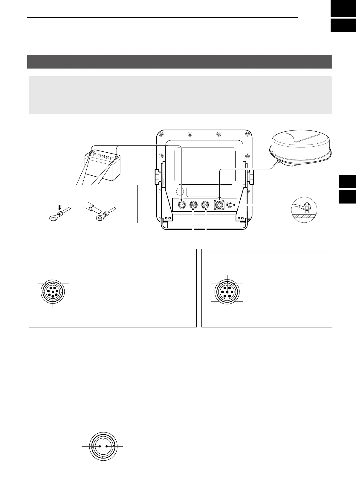
INSTALLATION AND CONNECTIONS
Basic connections
CAUTION:
• DO NOT turn ON the display unit until both the display unit and the scanner unit are completely installed and
connected.
• NEVER connect anything other than the supplied scanner unit.
• An incorrect cable connection may damage the display unit.
D Power source
You can directly connect the display unit to a 12 V or
24 V DC battery without a DC-DC converter or any
internal modications.
(Power source requirement: 10.2 ~ 42 V DC)
Connect the DC power cable as shown above.
Black: _
Red: +
PWR connector
D Grounding
To prevent an electrical shock or other problems,
ground the display unit through the [GND] terminal.
For the best results, connect a heavy gauge wire or
a strap to the nearest grounding point on the vessel.
The length of the wire or the strap should be as short
as possible.
GND
Ground
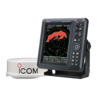
Supplied scanner unit
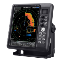
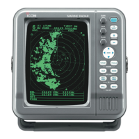
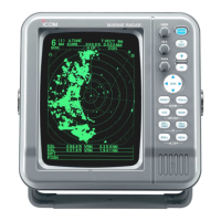
Display unit
Power source
12 or 24 V DC
PWR
Black: _
Red: +
Use the terminals shown below for the
cable connections.
Crimp
Solder
NMEA 1: AIS data input / Bearing data input
(AIS IEC61162-2 / NMEA0183, N+1, AUX format)
(Rear panel view)
NMEA 2: NMEA 0183 data Input/Output
(Rear panel view)
DC power cable
System cable
NMEA connector (PLT-168-P-R) NMEA connector (PLT-167-P-R)
1AIS input (+)
2ALM 12V
3NMEA 1 input (+) or AUX input (+): DATA
4NMEA 1 input (–) or AUX input (–): DATA
5N+1(+): data input or AUX input (+): CLOCK
6N+1 input (–) or AUX input (–): CLOCK
7AIS input (–)
8ALM output
1NMEA 2 output (+)
2NMEA 2 output (–)
3NMEA 2 input (+)
4NMEA 2 input (–)
5DSC input (+)
6DSC input (–)
7GND
8
1
2
3
7
6
5
4
7
1
2
3
6
5
4
• NMEA 1/2 inputs, NMEA 2 output, DSC input: 4800 bps
• AIS input: IEC61162-2 38400 bps
 Loading...