50
INSTALLATION AND CONNECTIONS
9
1
2
3
4
5
6
7
8
9
10
11
12
13
14
15
16
17
18
19
20
21
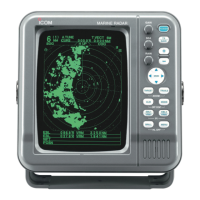
Installing the scanner unit (Open array types)
D Wiring the system cable
1. Remove the 4 bolts on the bottom of the
scanner
body using the supplied allen wrench
(1), and
open the top cover. (2)
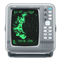
2. Remove 2 screws and cable clamp.
Screw
Cable
clamp
3. Remove the sealing nut outside the scanner unit.
4. Pass the system cable through the sealing nut,
sealing tube, scanner body, and the cable clamp
base.
Sealing nut Sealing tube
Cable clamp
base
System
cable
Scanner body
To the
display unit
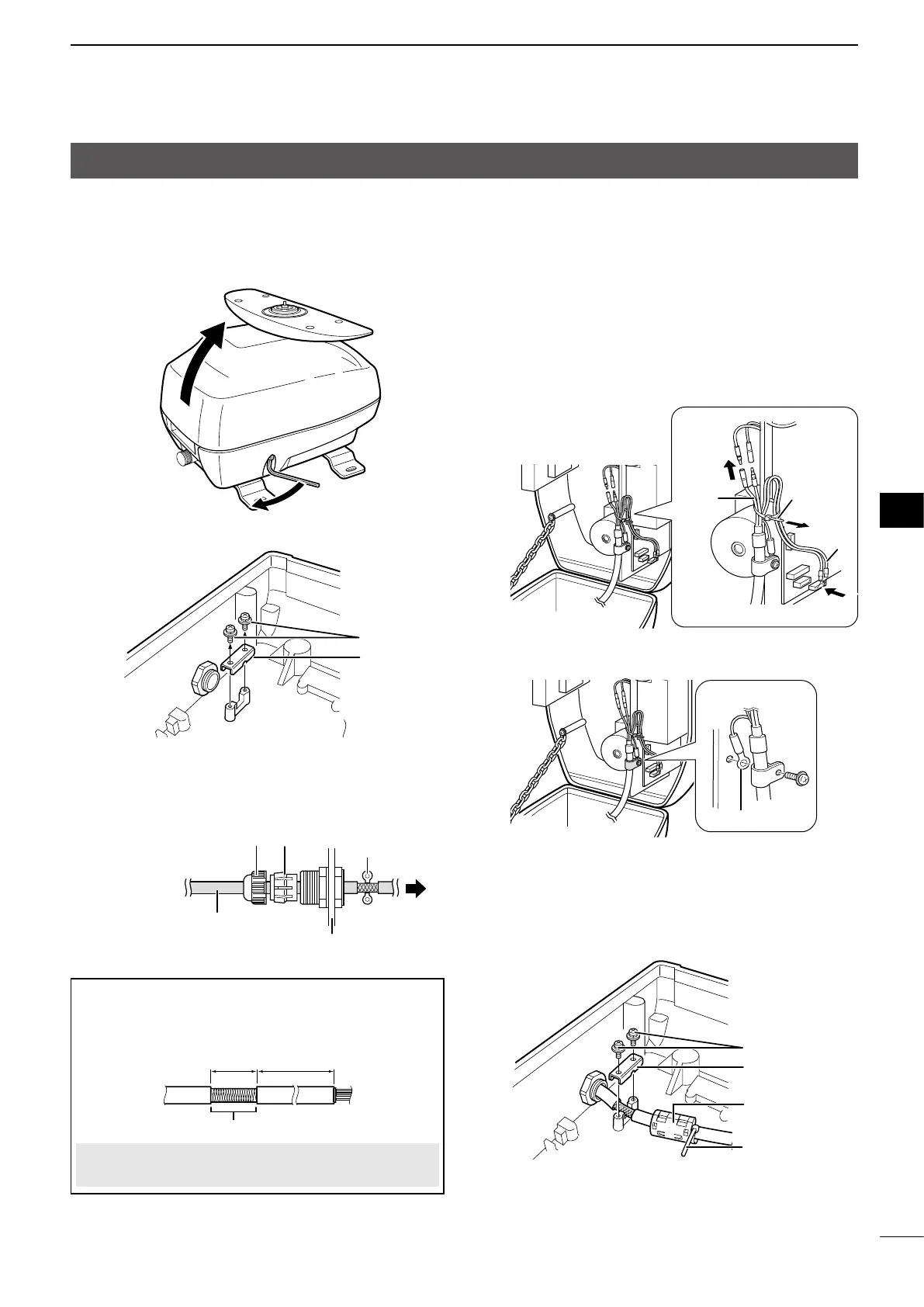
When using an optional OPC-2340 system cable:
Strip off a part of the outer sheath of the system
cable, as shown below.
(0.71±0.08 in)
(16.14±0.2 in)
Display ←
unit
→ Scanner
unit
Strip off
CAUTION: DO NOT cut the inner shield wire when
stripping off the outer sheath.
1
2
5. Connect the system cable to the scanner unit.
1Pass the power cables (black and red) of
the system cable through the looped cable
tie, and then connect them to the power unit
connectors.
2Carefully insert the PA cable (black and white)
connector into the PA unit connector, as shown
below.
3Secure the looped PA cable with the looped
cable tie.
1
3
2
Power
cable
Cable tie
PA
cable
6. Ground the system cable to the chassis with the
screw, as shown below.
Ground wire
7. Fix the system cable with the cable clamp near the
sealing connector and two screws.
Attach the ferrite EMI lter close to the sealing
connector of the system cable, and then secure
the cable tie beside the ferrite EMI lter, as shown
below.
Screw
Cable clamp
Ferrite
EMI lter
Cable tie

 Loading...