3
1
PANEL DESCRIPTION
Function display
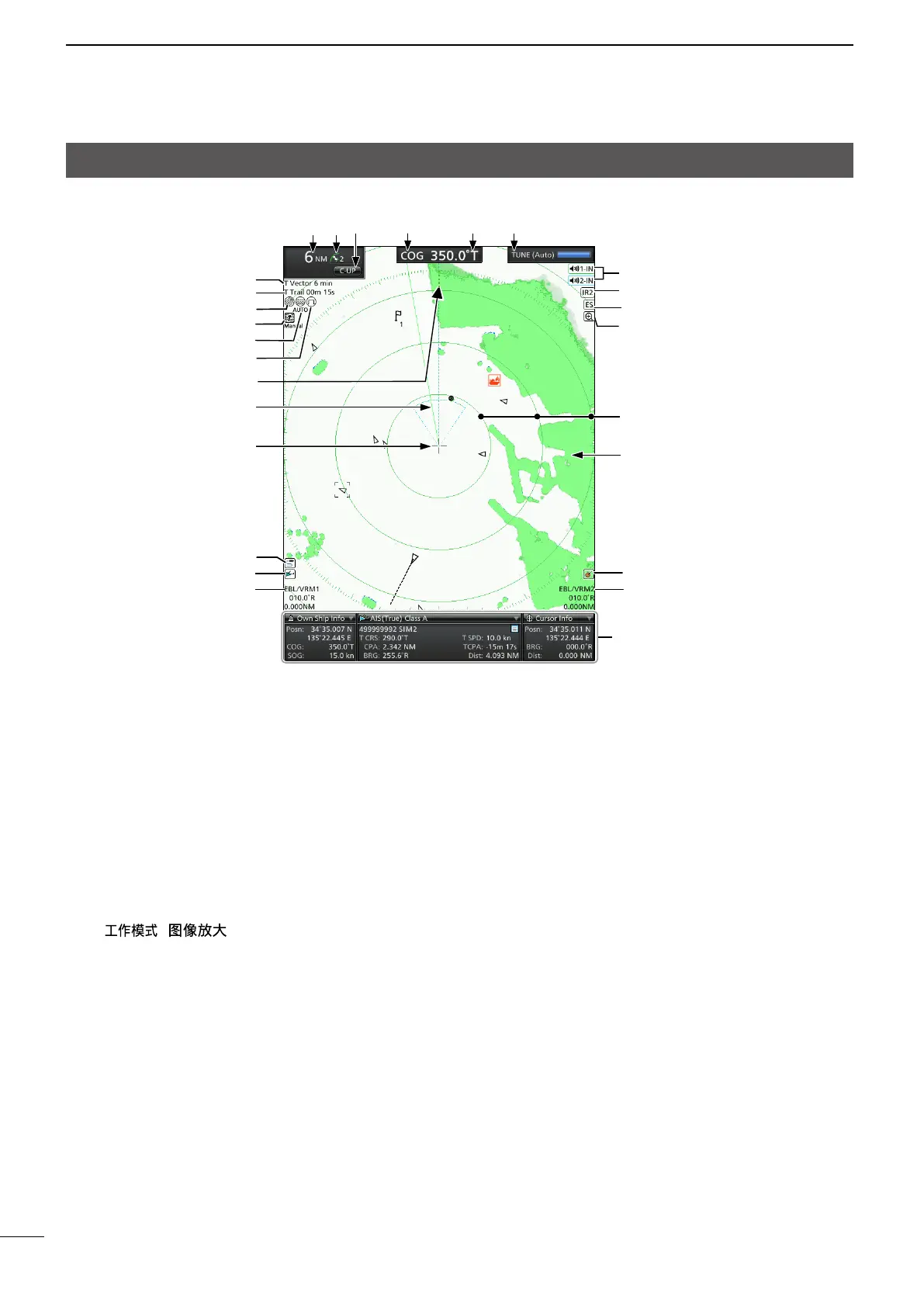
1 SCREEN RANGE READOUT (p. 6)
Displays the range of the current screen.
NM: Nautical miles
km: Kilometers
SM: Miles
2FIXED RING RANGE READOUT (p. 17)
Displaystheintervalrangeofthexedring.
3MODE INDICATOR (pp. 9, 11)
Indicates the Screen mode. “(3D)” is displayed
while in the 3D view mode.
z Push [MODE (ZOOM)]/
[ ( )] to select.
H-UP / H-UP (3D): Head-up
SH-UP / SH-UP (3D): Stabilized Head-up
N-UP / N-UP (3D): North-up
C-UP / C-UP (3D): Course-up
TM / TM (3D): True Motion
4 HEADING INDICATOR (p. 10)
Displays the heading readout.
HDG:
Heading
Indicates the heading of the vessel’s bow
in a clockwise direction from north.
L Displayed when “Bearing Input” in the Initial
menu is set to “NMEA,” “AUX” or “N+1.”
COG: Course Over the Ground
L Displayed when “Bearing Input” in the Initial
menu is set to “GPS” or “GPS-L.”
5BEARING REFERENCE (p. 10)
Displays the bearing reference.
T: True bearing
M: Magnetic bearing
6TUNING MODE INDICATOR
Displays the Tuning mode and the Tuning level.
“Standby” is displayed while in the Standby mode.
TUNE (Auto): Auto tuning
TUNE (Manual): Manual tuning
7VECTOR INDICATOR
Displays the basis of vector reference and the
vector time.
T Vector: True vector
R Vector: Relative vector
8TRAILS INDICATOR (p. 14)
Displays the Trail Reference and the Trail Time.
L Echoes remain, with gradation, during the period of
trail time on the screen. (Except for the trail time: ∞)
L Progressing time counter starts counting until the timer
reaches the trail time.
T Trail: True trail
R Trail: Relative trail
1 5 623 4
8
Information boxes
7
L The screen below is only an example.
9
 Loading...