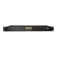
Distribution Series 3 Dual Bus
855-314-002_Rev2.0_Instruction Manual
stripping and terminating 16–28 AWG alarm wiring and connecting
to the five Site Alarm Inputs on the 10-pin removable Alarm Input
Plug, if desired. These inputs may be configured to activate the
panel Alarm outputs or send an alarm e-mail on network connected
units. The external sensor contacts must be voltage free as a small
sense current is supplied from the panel Alarm Input pins to detect
the external contact open or closed state. Refer to Section 4.9 for
more information on how to configure and use the five Site Alarm
inputs.
Table 3. Site Alarm Inputs
Site Alarm Input Function
Risk of personal injury or damage to equipment and
property. Always observe the following:
• DC-AC Inverters should not be connected to the outputs of
any ICT Distribution Series panel. DC-AC Inverters create
significant inrush current and may damage the circuitry or
interfere with the operation of power distribution panels that
they are connected to. Connecting an inverter in this way
may void the product warranty. ICT recommends connecting
a DC-AC inverter to the battery bank.
• Ensure that the combined current draw on the outputs does
not exceed the output capacity of the bus (100 amps).
• Leave breakers turned off until the software has been
configured (see Section 4).
Make connections to the load using wire and connectors appropriately rated
for the maximum output current capability of the unit.
An output (labelled OUT) and return (labelled RTN) are provided for each
channel.
 Loading...