The unit may also be configured to send an alarm e-mail to multiple user e-
mail addresses for any of the alarm conditions (see Section 4.9) (no e-mail
will be sent if power is disconnected from the unit, due to loss of network
control).
4.0 OPERATION: GRAPHICAL USER INTERFACE
Connect to the Distribution Series 3 via Ethernet for full remote monitoring
and control using any standard web browser on a network connected
computer or phone. No additional software is required.
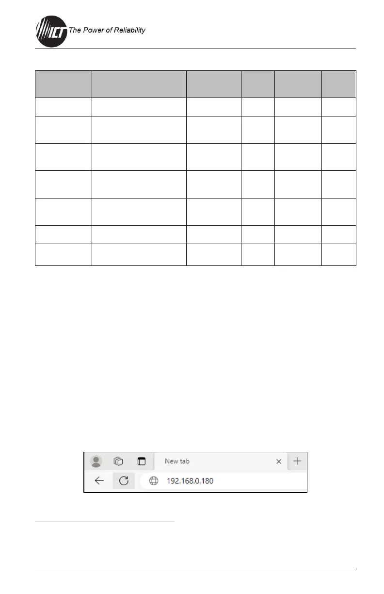
4.1 Log In/Log Out
1. Connect to the Distribution Series 3 by entering the IP address of
the unit in the location/address field of the browser as shown:
The Bus Alarm LED and Bus Alarm contact are enabled for Breaker alarms as the factory default setting;
all other alarms must be enabled in the appropriate setup page of the GUI by selecting the “Activate Alarm
Form-C Contact” check box for each alarm.
 Loading...