52 PRT-CTRL-SE Protege SE Integrated System Controller Installation Manual | June 2017
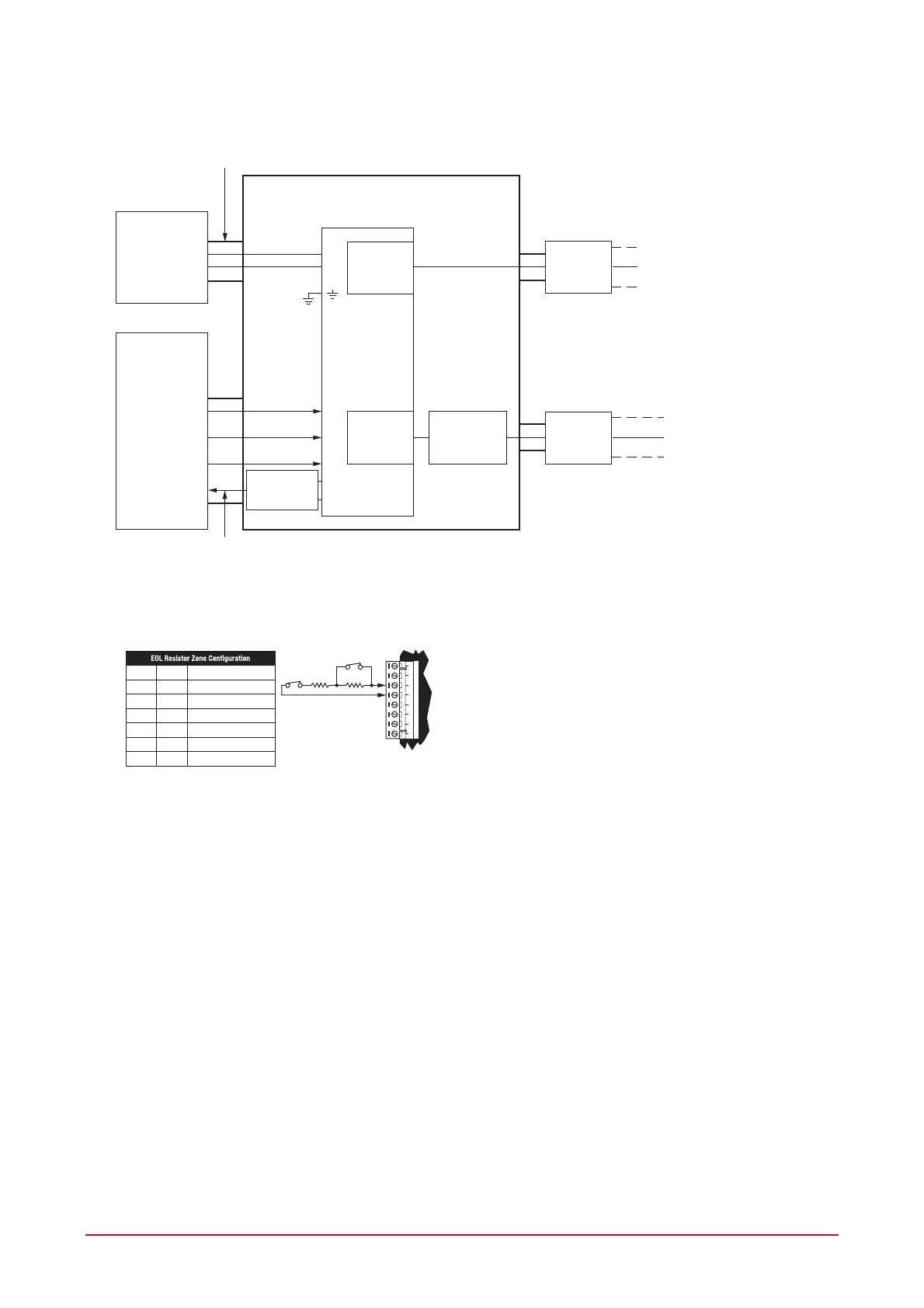
ETHERNET
DIALER
ENCLOSURE
FIRE
SUPERVISORY
TROUBLE
FIRE ALARM PANEL
Z1
Z2
Z3
PRT-CTRL-SE
COM STATUS / FB
MARCUS M4758CT
Hardwire Transformer
AC
AC
CAN/ULC-S559
PRT-CTRL-SE
PASSIVE COMMUNICATION
INTERNET
TELECOM
EQUIPMENT
TELECOM
EQUIPMENT
Modem Interface
Surge Protector
L-Com HGLN-D1DT
24h Standby / Backup
Required for Telecom
Equipment
PSTN
Note: All cables shall be protected within metal conduits.Metal Conduit
* If installation requires Fire Alarm Panel local supervision, a ULC S527 listed relay module (such as the EDWARDS CRCRL RELAY) must be used to trigger input zone on fire alarm control panel.
The relay module must be able to meet supervision requirements of the input zone or be mounted within 18m of the fire alarm control unit in conduit.
* Fire zones shall be separated from burglar zones through area partitioning.
* Fire zones Z1-Z3 shall be used exclusively for fire monitoring and cannot be programmed to activate bell outputs (B1/B2)
* EOL resistor must be installed at the Fire Alarm Control Panel Output.
AUX
P3 or P4
Dry Contacts
EDWARDS
CRCRL
RELAY
POS+
NEG -
Typical Zone Circuits
Value 1 Value 2 Monitored Status
1K 1K Open, Close, Tamper, Short
6K8 2K2 Open, Close, Tamper, Short
10K 10K Open, Close, Tamper, Short
2K2 2K2 Open, Close, Tamper, Short
4K7 2K2 Open, Close, Tamper, Short
4K7 4K7 Open, Close, Tamper, Short
+AUX- Z1 COM COMZ2 Z3 Z4
N.C
Tamper
N.C Zone Contact
Value 2 Value 1
Fire Zone Inputs and Outputs
Fire Zone inputs must be programmed as follow:
FACP Fire Alarm Signal zone type must be programmed as Fire
Supervisory Trouble Signal zone type must be programmed as 24 Hr Silent
Trouble Signal zone type must be programmed as 24 Hr Silent
Please refer to the section Zone Type Alarm Options in the Protege System Controller Reference Manual
(227-4045-500)
All fire zone inputs must be placed into an area and this area must be armed. Please refer to the section
Area in the Protege System Controller Reference Manual (227-4045-500)
COM Status
FACP system with a COM STATUS input must have this input connected to the P3 or P4 output of the
panel and the selected output must be programmed as the Report OK PGM in the Contact ID Service.
Please refer to section Report OK PGM Option in the Protege System Controller Reference Manual
(227-4045-500).
Fire zones Z1-Z3 shall be used exclusively for fire monitoring and cannot be programmed to activate bell
outputs (B1/B2).