Model 252
Label Printer/Applicator
Operators/Technical Manual
6
8. Electronics Assembly
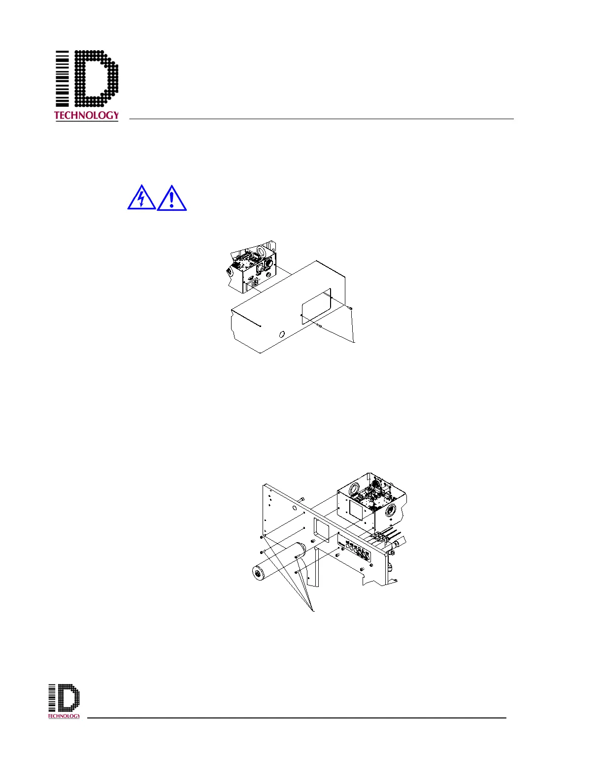
Start by removing all power and air from the applicator. Next, remove the back cover from
the applicator using a 3mm hex wrench.
Before attempting to service machinery, the machine must be turned off
and the power and air locked out.
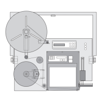
Disconnect the external components with removable connections from the PCB (Solenoid
valves, Rewind motor, Low Label Sensor, etc.) and carefully remove them through the
grommeted holes. Disconnect the permanently attached power cord from the print engine.
Loosen the screws securing the “D” style connectors to the rear panel and remove the cable
assemblies. Disconnect the network connection and the system status output connector if
equipped. Using a 3mm hex wrench, remove the four M4 socket head screws securing the
electronics assembly to the baseplate.
ELECTRONIC MODULE
MOUNTING SCREWS