Model 252
Label Printer/Applicator
Operators/Technical Manual
19
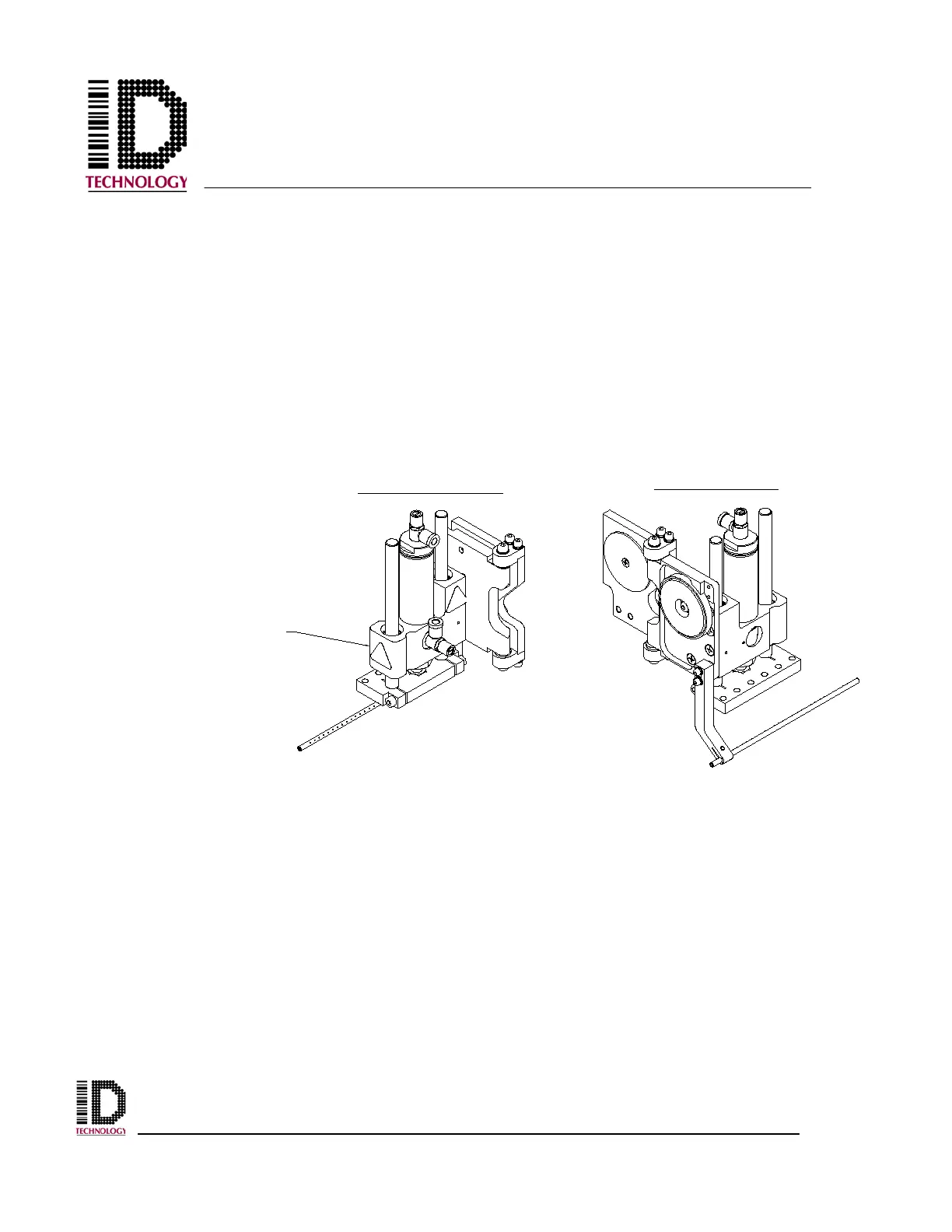
3.10 Service Tamp Assembly
The service tamp assembly, like the standard tamp assembly, allows a direct contact
method for applying labels to products or packages. The additional service feature allows
the tamp pad and air cylinder/bearing block portion of the tamp assembly to be rotated in
an outward direction. This allows for easier access when servicing the engine or
performing tamp pad change-over operations. The service tamp module is available in
2”, 4”, 6”, and 8” stroke lengths. Refer to the standard tamp assembly positioning
adjustment instructions to adjust the service tamp assembly. Unlike the standard tamp
assembly, the air assist bracket and tube is included as part of the service tamp assembly.
Once again, adjustments are done in the same way as the standard tamp assembly. Refer
to the applicator specific Tampjet Upgrade for a non-contact option.
Specific application requirements may require the use of another type of tamp module.
OPERATING POSITION
SERVICE POSITION
TO ROTATE
GRIP HERE