Model 252
Label Printer/Applicator
Operators/Technical Manual
53
5.14 Setting up Tamp Applications
5.14.1 Setting the Tamp Position
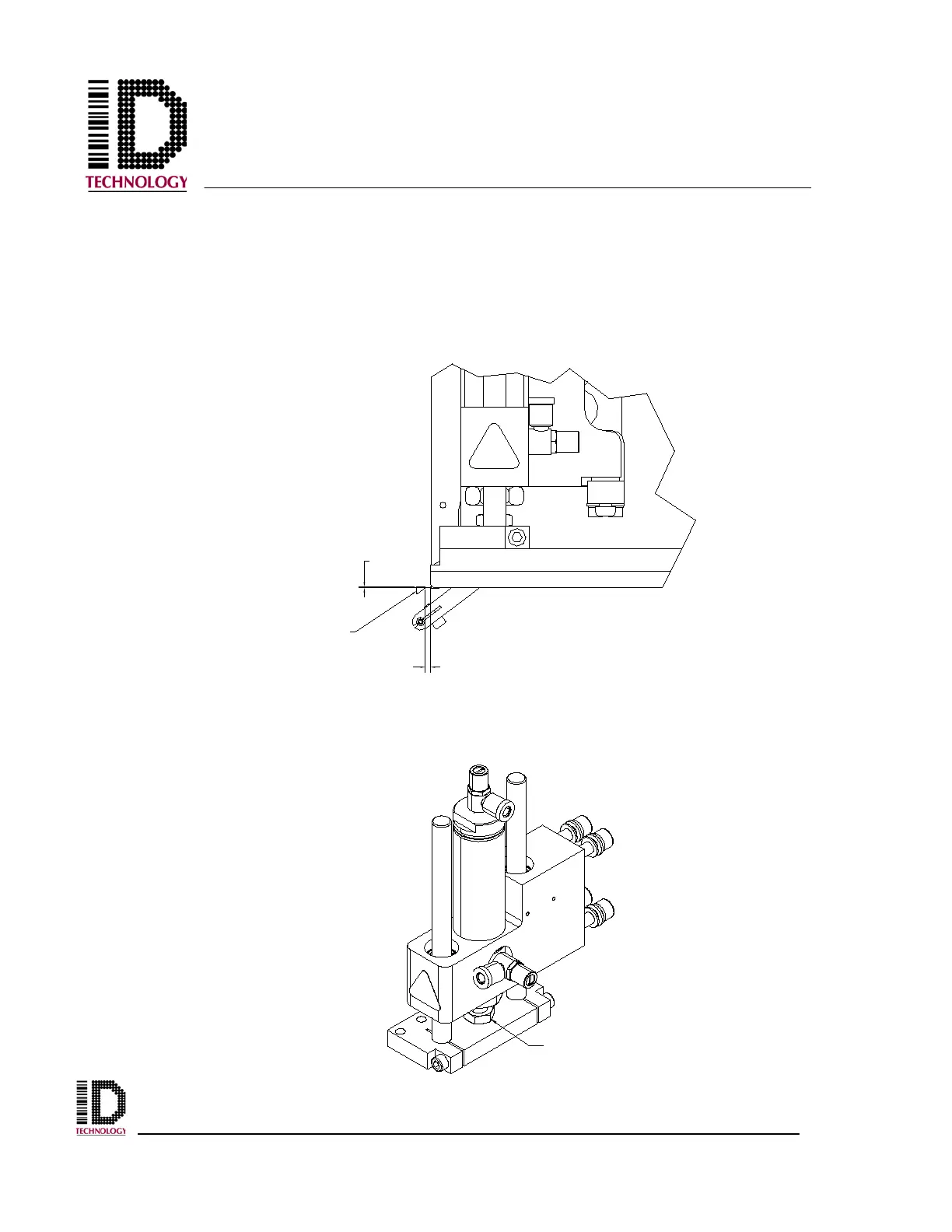
Begin by loosening the four M8 bolts holding the tamp module to the faceplate using a
6mm hex wrench. Slide the tamp module in the mounting slots until the tamp pad is
approximately 1/8” from the peel tip. Be sure the tamp module is straight up and down
then re-tighten the mounting bolts.
With the cylinder all the way home, note the position of the chamfer to the peel edge.
The top surface of the peel plate should, if drawing an imaginary line, intersect the tamp
pad midway up the chamfer (the angled cut across the front edge). If the position is not
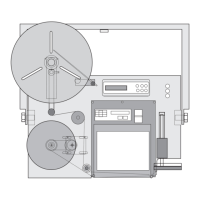
correct, use a small adjustable wrench to loosen the cylinder adjust nut.
1/8"
HALF OF
CHAMFER
PEEL EDGE
CYLINDER
ADJUST NUT