Model 252
Label Printer/Applicator
Operators/Technical Manual
17
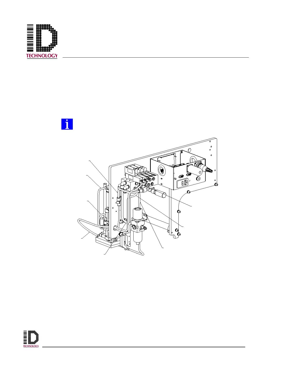
Next, locate the tubing that was supplied with the tamp module. There should be a black,
blue, yellow, and grey tube in 1/4” diameter and a black tube in 5/16” diameter. The
5/16” black tube should be routed from the “P” port fitting of the pneumatic assembly
manifold to the filter regulator assembly. The filter regulator should be mounted in a
convenient location near the applicator where it will not interfere with operation and can
easily be drained. Multi-position mounting holes are provided on the u-arm for this
purpose.
Be sure to mount the filter regulator with the bowl and drain pointing
straight down. Mounting at an angle or upside down will cause the
regulator to function incorrectly.
Shown with U-Arm removed for routing illustration.
BLACK TUBING
(1/4")
GREY TUBING
YELLOW
TUBING
YELLOW
TUBING
BLACK TUBING
(5/16")
BLUE TUBING
BLACK TUBING
(1/4")
GREY TUBING