Model 252
Label Printer/Applicator
Operators/Technical Manual
41
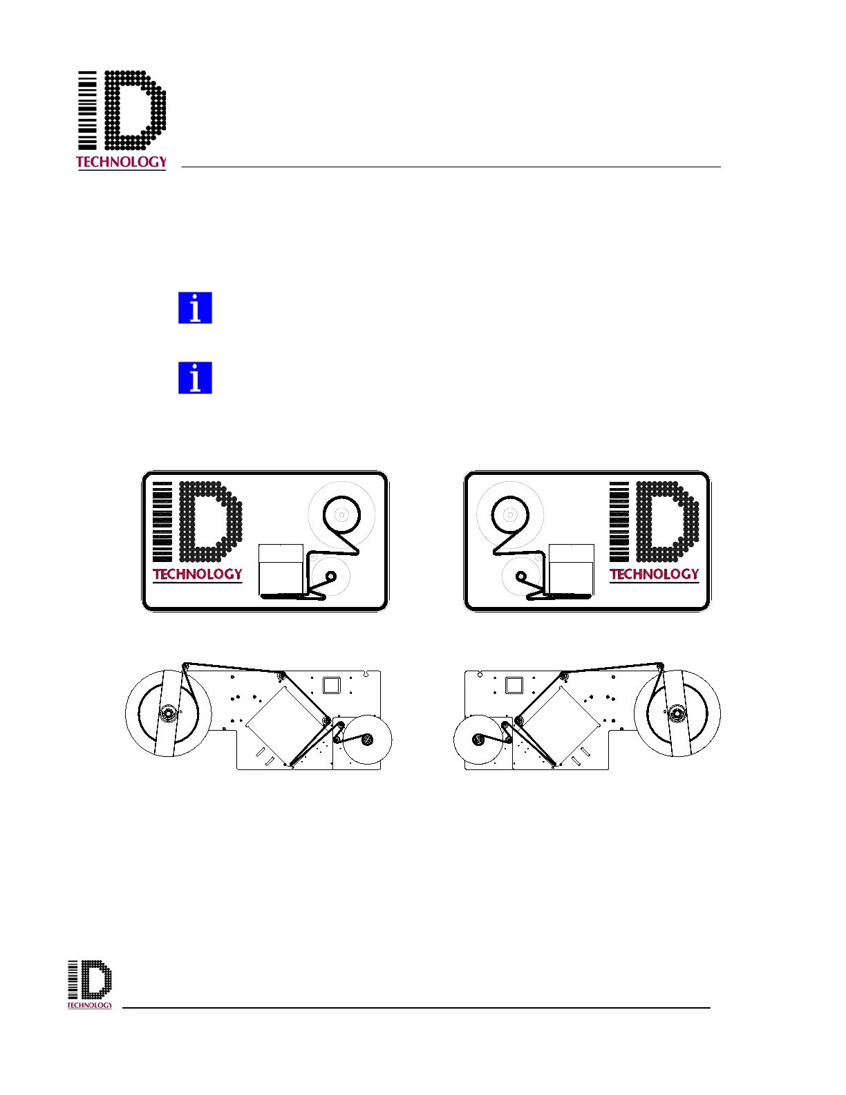
From the exit of the print engine or apply module, pass the web around the
rewind dancer roller, around the 1” idler roller and then back over the roller
to the waste take up. Continue to wrap the liner around the waste take up starting
from the bottom. Install the lock pin to attach the liner to the waste take up.
Align the front edge of the first label on the web with the peel edge.
On the applicator, be sure the liner passes between the peel edge and the air
assist tube. If the liner goes around the tube, the label will not dispense
properly onto the vacuum pad.
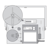
The end of each roller along the label web path has a washer on which you
will find a directional arrow. The arrow indicates the direction that the
label web should pass over the roller when correctly installed.
Refer to the appropriate label threading diagram for assistance as needed.
When a printer is used, follow the instructions for the print engine to install printer ribbon
in the unit. Once the labels have been loaded onto the printer/applicator, the application
specific configuration can be done.
Apply power to the printer/applicator and the print engine. Press the Applicator
Online/Offline icon to take the system offline. Connect the air supply to the filter
regulator and adjust to the appropriate pressure as shown in the Setting the Pressures
section.
252N LH THREADING DIAGRAM 252N RH THREADING DIAGRAM