15
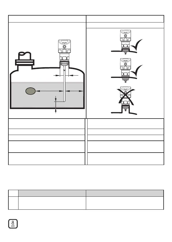
7.2.1 Minimum distances and minimum connection piece diameter
Fig. 7-1 Fig. 7-2
Without adjustment
A1
B
A2A3
D
Installation distances with adjustment (→
7�2�7)
Installation distances without adjustment
A1: 10 mm A1: 10 mm
A2: 20 mm A2: 50 mm
A3: 20 mm to tank structures (B)
50 mm to other sensors type LR
A3: 50 mm to tank structures (B)
50 mm to other sensors type LR
D:
ø 30 mm if installed in a connection
piece
D: No connection piece allowed
according to fig� 7-2
7.2.2 Installation in pipes
► Only install the unit in metal pipes�
► The internal pipe diameter d must at least have the following value:
With adjustment(→ 7.2.7) Without adjustment
d
ø 30 mm
ø 100 mm with [MEdI] = [HIGH]
ø 250 mm with [MEdI] = [MId] (→ 11.2.3)
► If possible, mount the unit off-centre (eccentrically)�
Depending on the operating conditions (flow) and mechanical design of
the pipe the use of centring pieces is recommended (→ Accessories).