29
8 Electrical connection
The unit must be connected by a qualified electrician�
The national and international regulations for the installation of electrical
equipment must be adhered to�
Voltage supply according to SELV, PELV�
For marine applications (if approval available for the device), additional
surge protection is required�
► Disconnect power�
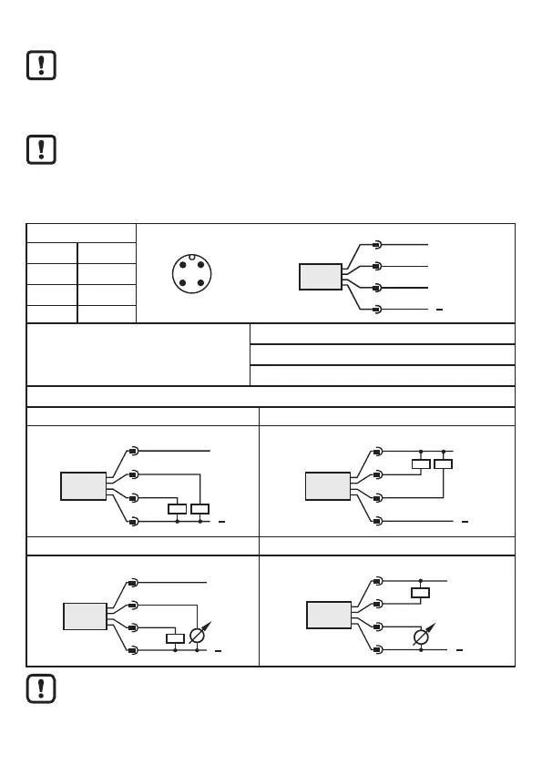
► Connect the unit as follows:
Core colours
43
2 1
BN
WH
BK
BU
4
1
3
2
OUT2
L
+
L
OUT1
BK Black
BN Brown
BU Blue
WH White
OUT1: Switching output / IO-Link
OUT2: Analogue output or switching output
Colours to DIN EN 60947-5-2
Example circuits
2 x positive switching 2 x negative switching
L
L
+
3
4
2
1
BU
BK
WH
BN
2: OUT2
4: OUT1
L
L
+
3
4
2
1
BU
BK
WH
BN
2: OUT2
4: OUT1
1 x positive switching / 1 x analogue 1 x negative switching / 1 x analogue
L
L
+
3
4
2
1
BU
BK
WH
BN
2: OUT 2
4: OUT 1
L
L
+
3
4
1
BU
BK
BN
2: OUT 2
4: OUT 1
2
WH
When operating voltage is applied to the unit for the first time, the basic
settings must be entered first (→ 11.2)� Only then is the unit ready for
operation�