11
UK
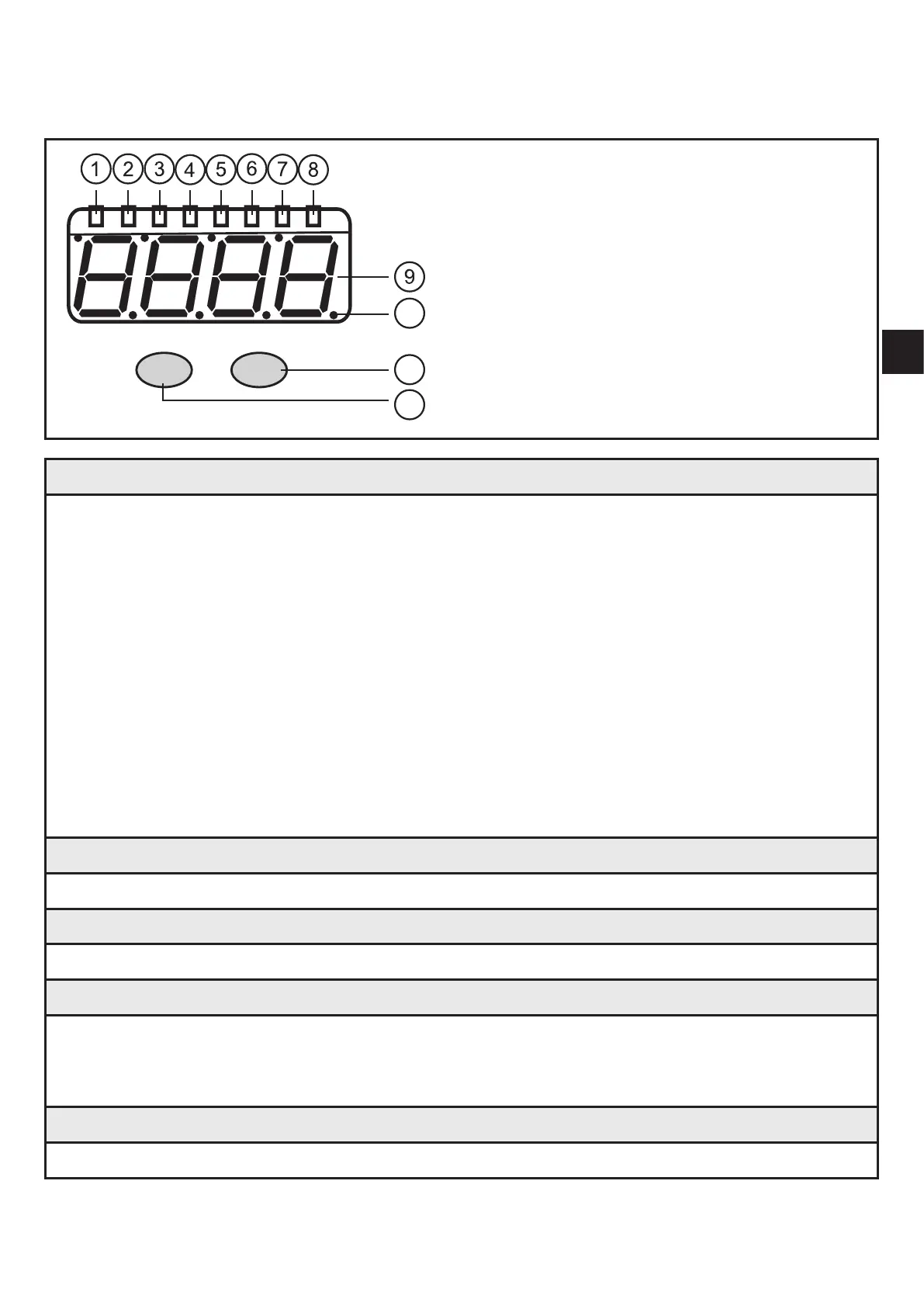
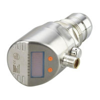
7 Operating and display elements
7.1 LED display
10
11
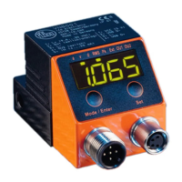
Mode/Enter Set
12
1...8: LED display
1: LED green a = vibration velocity a [g] or [m/s²]
2: LED green v = vibration velocity v [mm/s] or [in/s]
3: LED green d = not used
4: LED green RMS = average value
5: LED green Pk = peak value
6: LED green Ext = process value of the external transducer
7: LED yellow OU1 = pre-alarm active *)
8: LED red OU2 = main alarm active *)
*) The LED indicates the current alarm state (warning alarm, damage alarm)� The configu
-
ration of the corresponding output (OU1, OU2) as "normally closed" or "normally open" is
ignored�
9: 7-segment display green, yellow and red, 4 digits
- Display of the measured values
10: Points
- Lower points as decimal separators
11: Set button
Parameter setting mode
- Setting of the parameter values
- Change of display between the configured characteristic values
12: Mode/Enter button
- Selection of the parameters and acknowledgement of the parameter values�