7
UK
5 Electrical connection
The unit must be connected by a qualified electrician�
The national and international regulations for the installation of electrical equipment
must be adhered to�
Voltage supply to EN 50178, SELV, PELV�
Disconnect power before connecting the unit�
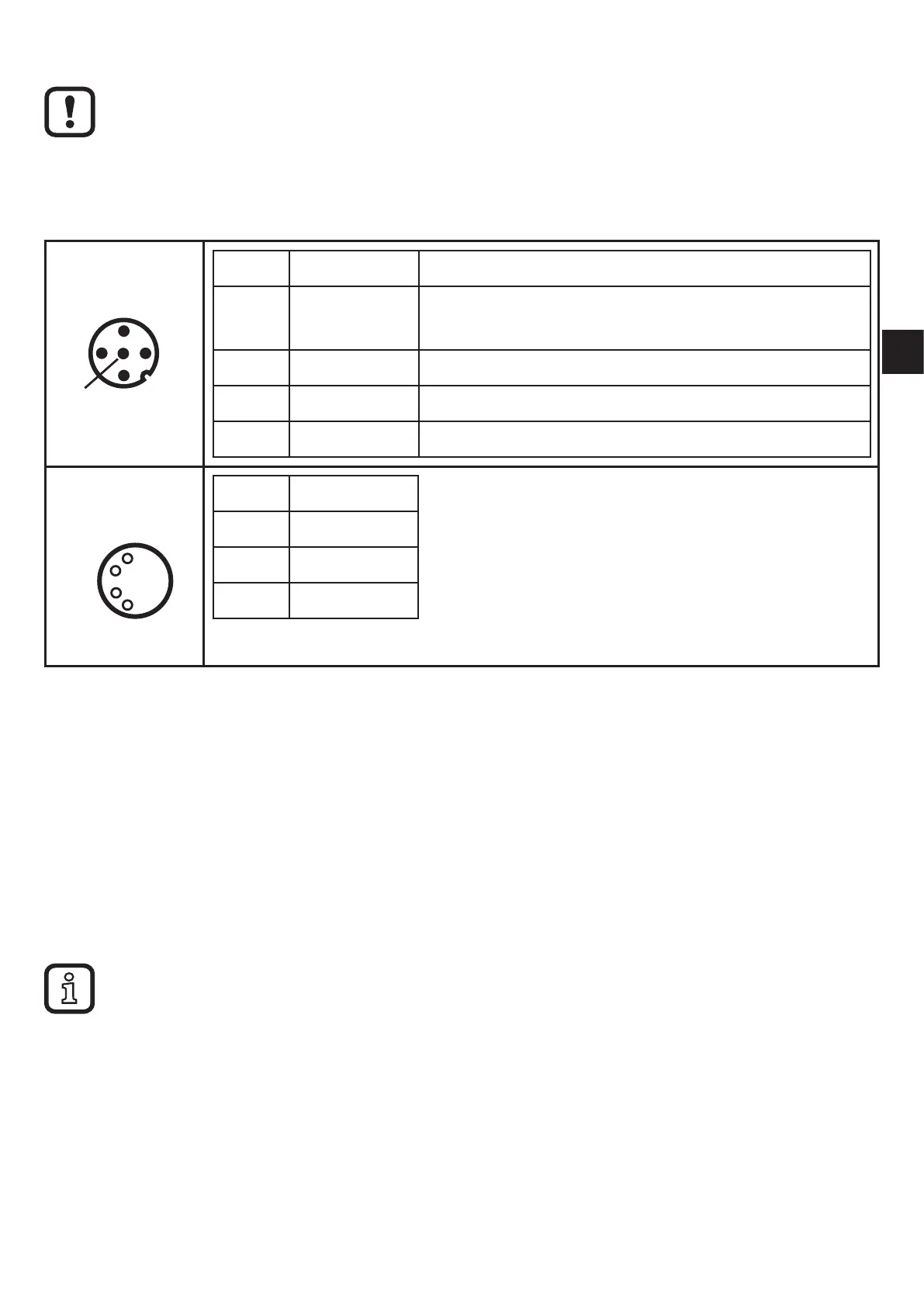
M12
Pin 1: L+ 9�6���30 V DC
Pin 2: Out 1 Switching output or current output
0/4���20/22 mA (configurable)
Pin 3: L -
Pin 4: Out 2 Switching output
Pin 5: IN Current input 0/4���20 mA
M8
Pin 1: VCC (5 V)
Pin 2: USB D-
Pin 3: L-
Pin 4: USB D+
5.1 M8/USB interface
► First connect the interface cable to the device and then to the USB interface of
the computer�
• Communication with the PC software for parameter setting of the objects to be
monitored, to read and reset the history data and to visualise measured data�
• The devices have a serial number that can be read via the PC software�
• The sensor can also be supplied via the USB interface�
Switching and analogue outputs are not supported if a USB power supply is used�
5.2 History values
The unit has an internal history memory� The memory interval can be configured
for each object via the PC software (min� 1 s)� The maximum value and optionally
the average value in this interval are stored together with the time stamp in the
memory�