Equipment Connections 91
6 Equipment Connections
The Protec P3000 is equipped with three electrical control connectors. The electrical
connections (head phone, I/O port and RS232) are located on the rear of the main
unit directly next to the socket for the mains cable.
6.1 I/O Port (Control Inputs and Outputs)
Through this connection some functions of the Protec P3000 can be controlled exter-
nally or measurement data or the of the Protec P3000 status may be communicated
to external equipment.
Through relay change over contacts the trigger levels as well as the operating mode
(Ready) of the Protec P3000 may be monitored.
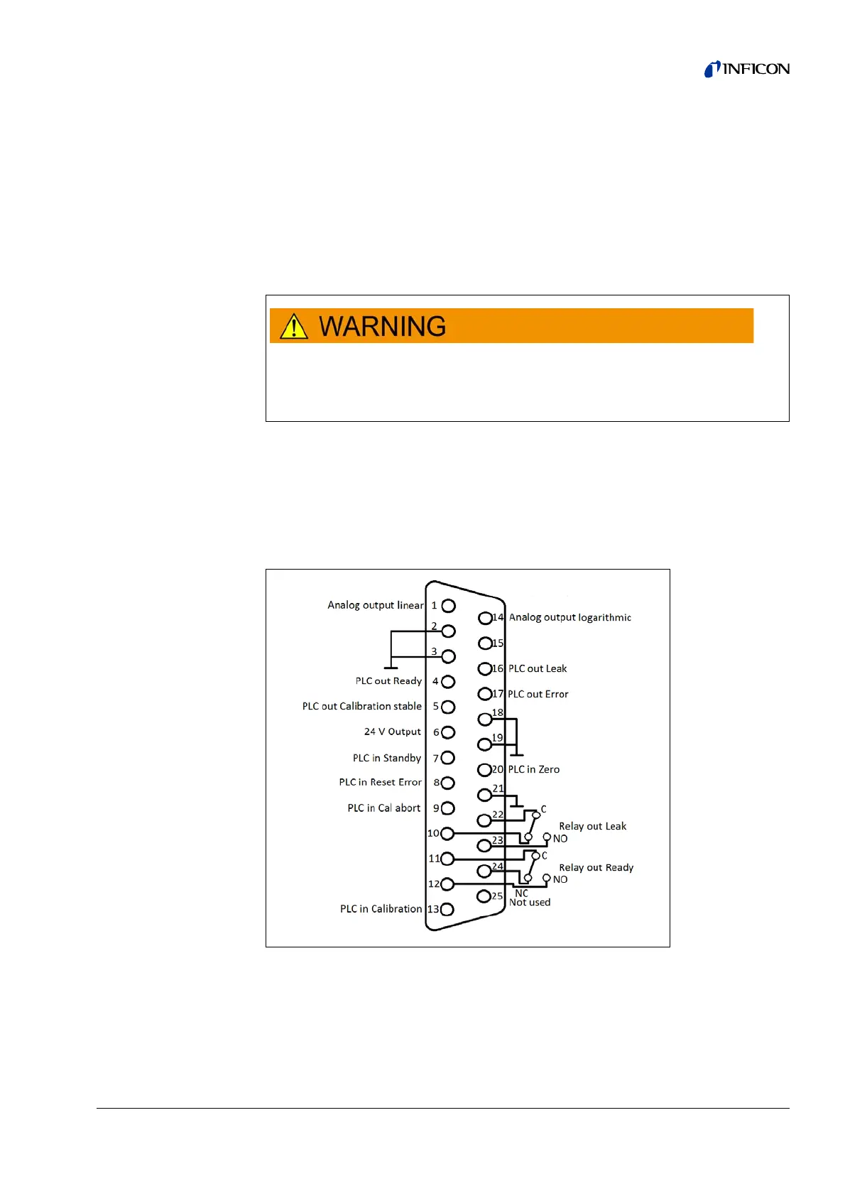
6.1.1 Ground connectors
Pin 2, 3, 18, 19 and 21 are ground connectors.
For all contacts of the I/O Port a maximum voltage of 60 V DC or 25 V AC
must not be exeeded or reached to ground or ground equipment conductors.
According to the type of in- or outputs lower voltages had to be accepted. For
this, please refer to the information given in the responding chapters.
Fig. 66 Default Pin Assignment