tinb29e1-c (2019-10) VGC083A_B.om 25
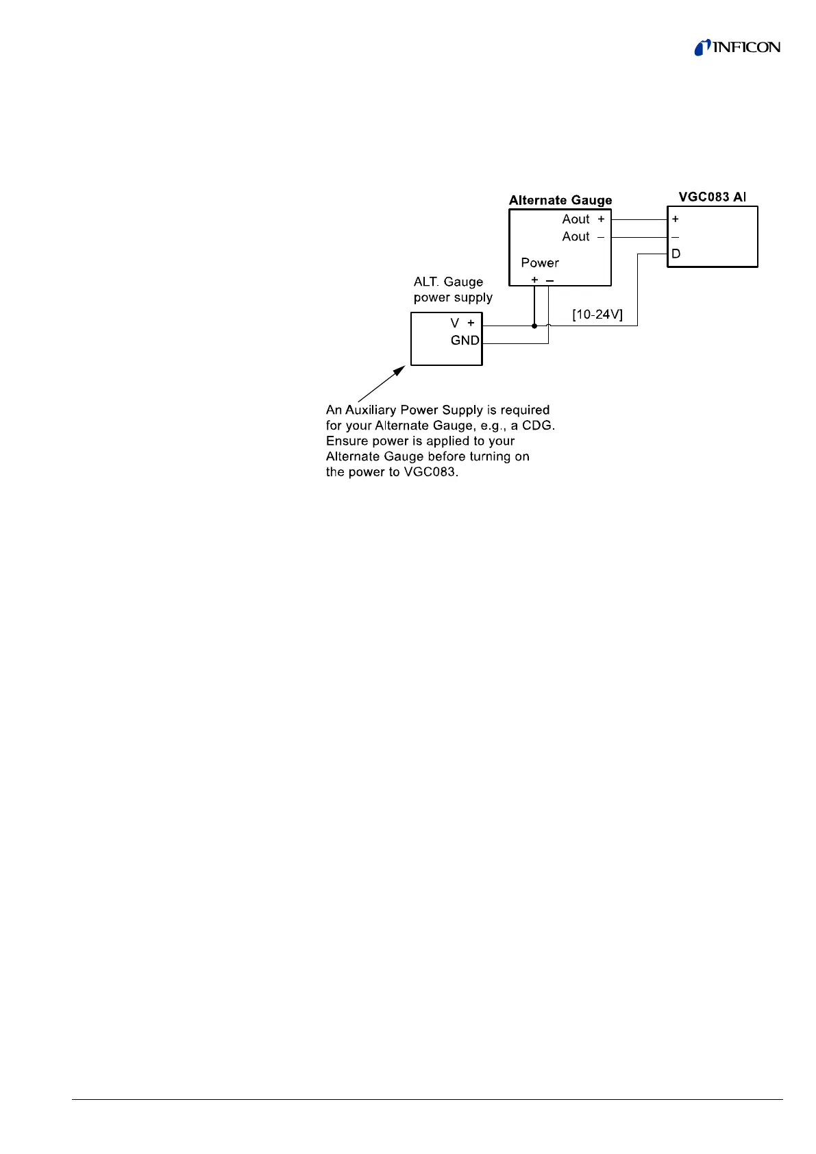
When using a capacitance manometer / diaphragm gauge or INFICON modules
such as the PGE300, PGE500, BAG302 as an ALTERNATE GAUGE, the gauge
must be connected to the VGC083 as shown below. The alternate gauge must be
provided power from an auxiliary power supply capable of providing the power re-
quired by the alternate gauge connected to the VGC083. The D contact is used in
this configuration to protect the IG from being turned on at high pressure in case
power to the alternate gauge is lost.
The IG can be controlled manually using the front panel soft-keys, via remote input
signals using the digital I/O connector or RS232/RS485 commands. The VCG083
can also be configured so that the IG sensor on/off is controlled by using the pres-
sure measurements from CG1, CG2 or the alternate gauge. If the user prefers di-
gital I/O as the means of controlling the IG, various control input and status output
signals are available from the 9-pin D-sub male DIGITAL I/O connector. The
DIGITAL I/O Connector also provides pin-pin compatible signals with the GP 358
vacuum gauge controller as well as compatible signals with the GP 307.
The DIGITAL I/O Connector provides three different types of signals as listed
below:
The IG sensor on/off, degas on/off and emission current selection can be set by
applying momentary continuity to ground. This requires a momentary ground of
less than 0.4 V (dc) at 10 µA for 25 msec (minimum) be applied. After this, the
input must be allowed to float higher than 3.5 V (dc) for 105 msec (minimum) be-
fore another low can be applied.
Input signal: Apply momentary continuity to ground to turn IG sensor on or off
Apply momentary continuity to ground to turn degas on or off
Apply momentary continuity to ground to switch Emission Currents
(100 μA or 4 mA)
The IG on/off status relay is also available as both normally open and normally
closed to indicate IG is on or off. This is an output signal to other external instru-
ments to confirm IG filament is on or off. The IG on / off status relay is a single
pole, double-throw (SPDT) relay rated at 1.0 A, 30 V (dc) resistive or 1.0 A,
30 V (ac) non-inductive.
A degas status or an error condition output signal is also available from the
DIGITAL I/O Connector. If programmed for DEGAS STATUS, this can be used as
an output signal to other external instruments to confirm that degas is on or off. If
programmed for an error condition, this can be used as an output signal to other
external instruments to confirm whether any error conditions exist.
Signal: Open collector transistor (ground emitter) rated at 40 V max. VCE,
50 mA IC max.
4.2.9 Digital I/O Connection
Signal Type A - Control Input
Signal Type B - Status Output
Signal Type C - Status output

 Loading...


