Edition 2.0 dated 20/11/2013
2-3 General Installation Information
2-3.1 Overview
This section of the manual provides general installation guidelines to assist you with the mechanical
installation of the MAXIM Series controllers.
2-3.2 General Installation Guidelines
The following installation guidelines are provided to ensure continued and reliable operation of the
MAXIM Series controllers:
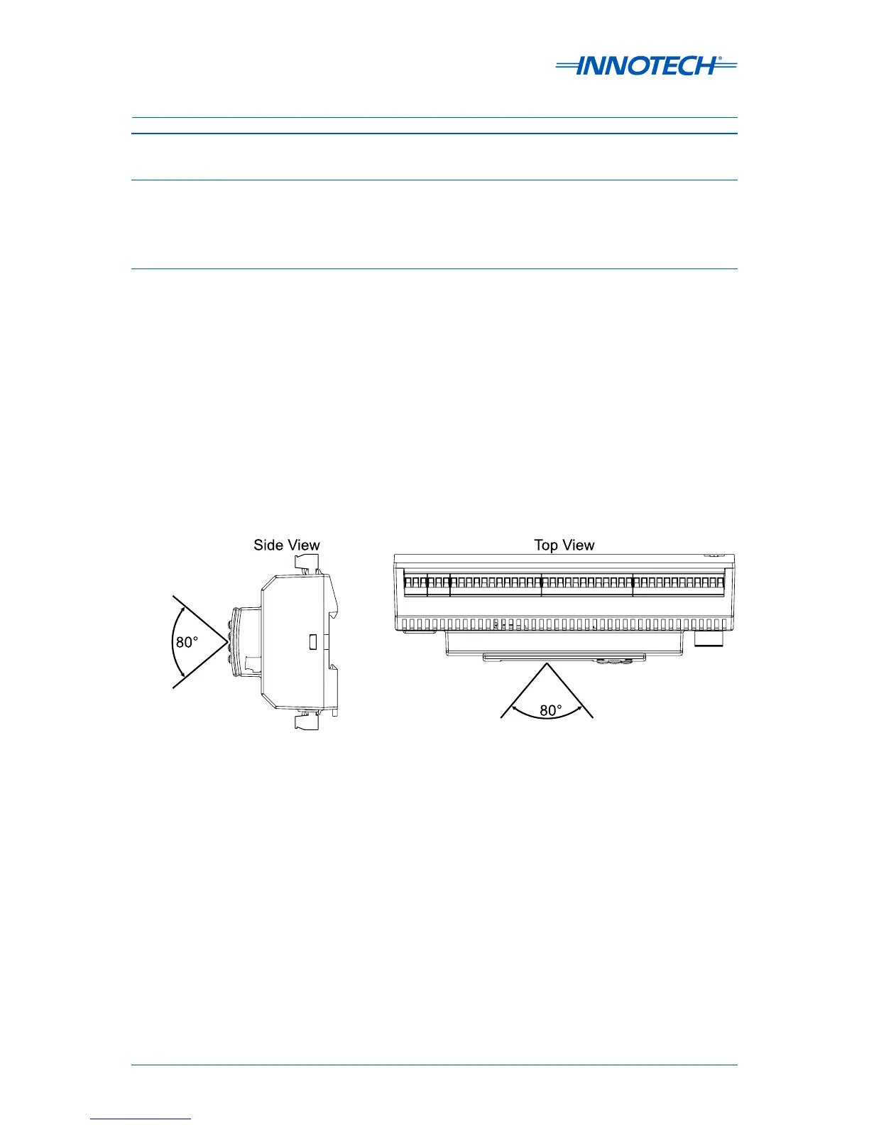
• The MAXIM I, II, III, and 1010 controllers should be installed in a position that provides easy
access to the optional HMI, and suicient room for power and input/output cabling. Placement
of the these controllers should account for the optimum viewing angle of the LCD, which is
approximately 80 ° vertically, and 80° horizontally, as illustrated in Figure 2-5 below.
• The controllers should not be exposed to high voltage, high current cables, or sources of strong
radio frequency emissions such as transmitter antenna cables.
• The ambient temperature of the MAXIM Series controllers at the installation site should not exceed
the normal operating temperature range recommended for the specific controller.
• The controllers should be installed in an area with minimum vibration and minimum exposure to
mechanical damage.
Figure 2-5: LCD Optimum Viewing Angle