EasyManua.ls Logo

Innotech MAXIM 1010 - 3-3.1 MAXIM I, II, III, and 1010 Controllers; Figure 3-2: MAXIM I Controller Terminal Connection Layout; Figure 3-3: MAXIM II Controller Terminal Connection Layout

Default Icon
60 pages
Print Icon
To Next Page IconTo Next Page
To Previous Page IconTo Previous Page
Loading...
MAXIM Installation Instructions
Page 26
© Mass Electronics Pty Ltd 2011
Edition 2.0 dated 20/11/2013
POWER
UNIVERSAL
INPUTS
DIGITAL RELAY
OUTPUTS
ANALOGUE
OUTPUTS
RS 232
PORT
3-3.1 MAXIM I, II, III, and 1010 Controllers
This section of the manual provides wiring information for MAXIM Series I, II, III, and 1010 controllers.
Information is provided on wiring a power source, and all associated inputs and outputs.
The general layout of the input and output terminals for each of these controllers is illustrated in
Figure 3-2 through Figure 3-5 below and on the next page.
POWER
UNIVERSAL
INPUTS
DIGITAL RELAY
OUTPUTS
ANALOGUE
OUTPUTS
NET & GLOBAL
COMMS
(RS485)
AO
Com
-
AO
1
+
AO
2
+
AO
3
+
AO
4
+
+
+ + + + +
- - - - - -
123456
UI UI UI UI UI UI
0V
24V
DO 1
Net
Comm
DO 2 DO 3 DO 4 DO 5 DO 6
Global
Comm
Shield
NO ComNOCom NO ComNOCom NO ComNO Com
+
-
+
-
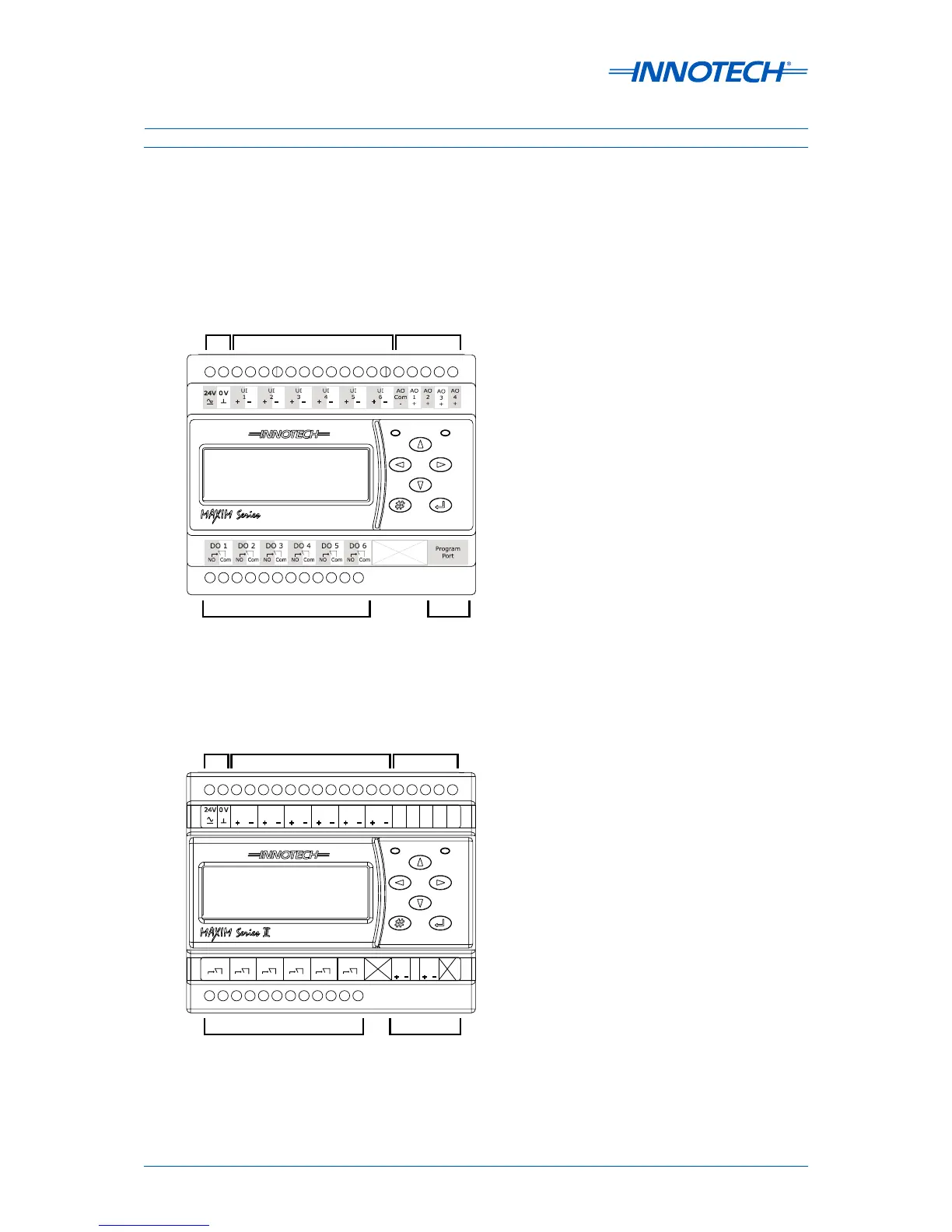
Figure 3-2:  MAXIM I controller terminal connection layout
Figure 3-3:  MAXIM II controller terminal connection layout

Table of Contents

Related product manuals